

Fixing device with field control characteristic
A fixed device and field control technology, used in high-voltage air circuit breakers, electrical components, electrical switches, etc., can solve problems such as high leakage current, and achieve the effect of reducing leakage current, high working voltage, and compact structure.
- Summary
- Abstract
- Description
- Claims
- Application Information
AI Technical Summary
Problems solved by technology
Method used
Image

Examples
Embodiment Construction
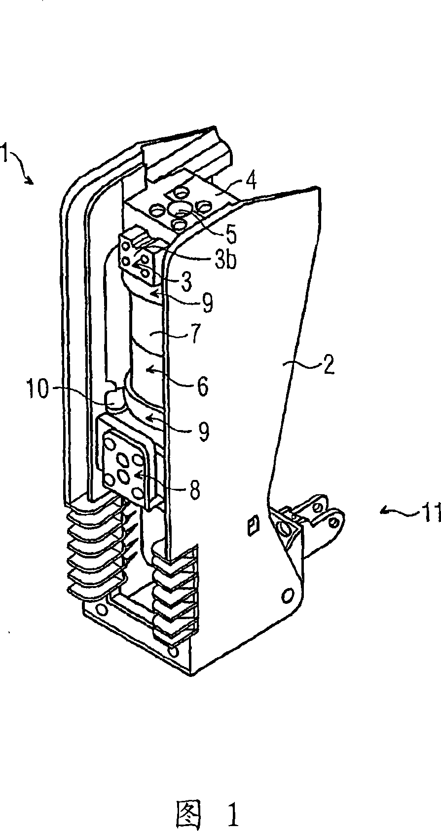
[0022] FIG. 1 shows a perspective view of a first exemplary embodiment of a switching pole 1 according to the invention. The switching pole 1 has a mechanically fixed support frame 2 , to which the pole head part 3 b of the input 3 is fixedly screwed. To this end, a transversely extending fastening beam 4 with fastening holes is used for screwing the pole head part 3b. Furthermore, the fastening beam 4 has a through-opening 5 through which fastening screws of a vacuum interrupter 6 as an interrupter at the input 5 can pass. The vacuum interrupter 6 consists of a hollow cylindrical ceramic housing 7 which consists of two parts which are connected to one another in the center of the ceramic housing forming an intermediate flange in the middle. The ceramic housing 7 is closed at the end by a metal cover, which cannot be seen in FIG. 1 , so that a vacuum-tight housing is formed. On the upper side of the vacuum switching tube 6 in FIG. 1 a fixed contact pin protrudes from the upp...
PUM
 Abstract
Description
Claims
Application Information