High-efficiency helical material pushing apparatus of horizontal helical centrifuge

A horizontal screw centrifuge and screw pusher technology, applied in centrifuges, centrifuges with rotating drums, etc., can solve the problems of incomplete solid-liquid separation, unfavorable liquid phase flow separation, etc., and achieve solid-liquid separation Thorough, improve the effect of separation, improve the effect of separation efficiency

Inactive Publication Date: 2008-08-13
JIANGSU HENGLIANG CENTRIFUGE MFG
View PDF0 Cites 4 Cited by
  • Summary
  • Abstract
  • Description
  • Claims
  • Application Information

AI Technical Summary

Problems solved by technology

[0003] At present, the existing screw pushers are all composed of a main shaft and a screw pushing piece, and the screw pushing piece is fixed on the outer surface of the main shaft with leads, and in the settlement zone, the outer circle of the screw pushing piece is the same, and the drying In the area, the screw pushing tablets are distributed in a conical shape. When the solid-liquid mixture is pressed into the space between the screw pushing tablets in the settling area from the discharge port, due to the high-speed rotation of the screw pusher, under the action of centrifugal force, the solid In the separation of liquid, the solid is distributed on the outer edge of the screw pusher, and gradually advances to the drying area under the rotation of the screw pusher, and finally pushes out from the solid phase port; while the liquid moves along the inner circle of the screw pusher. It flows to the liquid phase outlet at the leftmost end of the settling area. Since the screw pusher is a continuous strip, the solid phase is concentrated at the outer end of the screw pusher, which is not conducive to the flow separation of the liquid phase, so the solid-liquid separation is not complete. If To achieve a higher separation effect, it is necessary to further increase the speed of the screw pusher, which not only consumes more energy, but also improves the machining accuracy of the screw pusher, which is a common technology in existing decanter centrifuges problem

Method used


Image

  • High-efficiency helical material pushing apparatus of horizontal helical centrifuge

Examples


Embodiment 1

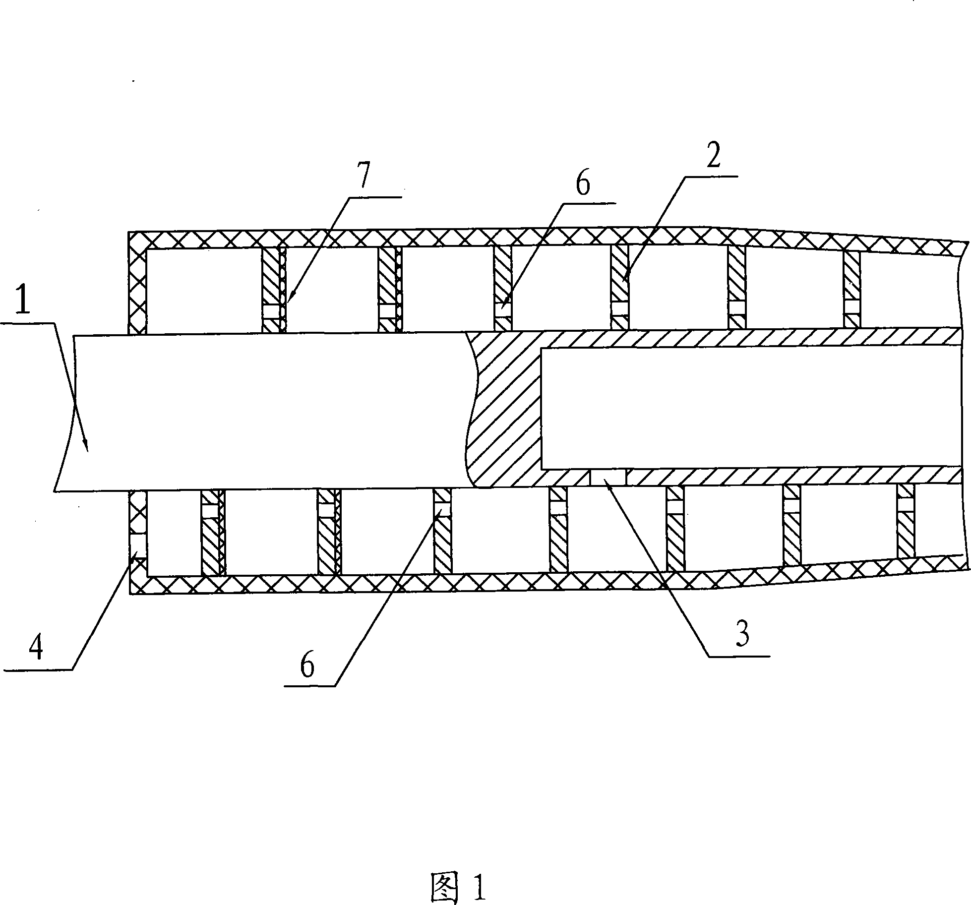
[0013] Embodiment 1: As shown in Figure 1, the high-efficiency screw pusher of the decanter centrifuge includes a main shaft 1 and a spiral pushing sheet 2, and the spiral pushing sheet 2 is distributed on the outer surface of the main shaft 1 with equal leads , in the settling area, the spiral pushing sheet 2 is distributed on the outer circle, and the main shaft 1 of this section is provided with a discharge port 3, and the leftmost end of the settling area is provided with a liquid phase outlet 4; in the drying area, the spiral pushing sheet 2 is conical. Shaped distribution, a solid phase outlet 5 is provided at the extreme end of the drying zone, and a liquid phase guide hole 6 is provided on the screw pushing sheet 2. The liquid-phase guide holes 6 are distributed on the inner side of the screw pushing plate 2, that is, on the side close to the main shaft 1, and the diameter of the liquid-phase guide holes 6 is 0.1-1.5 mm. A microporous gasket 7 is provided on the outer ...


PUM


Abstract

An obstruction preventing device of a horizontal spiral centrifuge comprises a feed tube, a main shaft and a frame. The feed tube is fixed on the frame and is mounted in the inner pore of the feeding terminal of the main shaft by an obstruction preventing sleeve. The inner pore of the obstruction preventing sleeve is a screw pore, and the right end thereof is provided with a flare shape. Since the feed tube is fixed on the frame and is mounted in the inner pore of the main shaft by an obstruction preventing sleeve, the solid-liquid mixture in the feeding chamber permeates into the space between the feed tube and the obstruction preventing sleeve during operation, the obstruction preventing sleeve spin with the main shaft to push the solid-liquid mixture permeating into the space between the feed tube and the obstruction preventing sleeve into the feeding chamber, so that permeation of the solid-liquid mixture into the space between the feed tube and the obstruction preventing sleeve is prevented effectively, friction of solid particle in the solid-liquid mixture to the feed tube is reduced, and obstruction between the feed tube and the main shaft is removed. In practical validation, during the centrifuge operation, it is provided with smoothly feeding, without obstruction, and the feed tube is not easily worn.

Description

technical field [0001] The invention relates to a decanter centrifuge, in particular to a screw pusher of the decanter centrifuge. Background technique [0002] Decanter centrifuge is a fully enclosed equipment capable of continuous solid-liquid separation. Compared with plate-and-frame filter press and belt filter press, it has the advantages of small footprint, low capital construction cost, large processing capacity, and high separation efficiency. The effect is good, there is no need to wash with water during work, it can realize clean processing, and it is easy to operate. Decanter centrifuges include casing, bearing housing, differential, drum, screw pusher, feed pipe, screw pusher is composed of main shaft and screw pusher, it is a good static and dynamic balance And its outer circular surface is equipped with a high-precision shaft-shaped part of the spiral piece, and one end of the main shaft is provided with a shaft hole for the feeding pipe to enter, and the lead...

Claims


Application Information

Patent Timeline
Patent Type & Authority Applications(China)
IPC IPC(8): B04B3/04B04B1/20
Inventor 吴锁华周建国颜兆华韩宁陈嵘
Owner JIANGSU HENGLIANG CENTRIFUGE MFG
Why Eureka
Try Eureka