Square steel pipe concrete and H-shaped steel beam nod connection structure

A technology of I-shaped steel beams and concrete columns, which is applied in the structural field in the field of construction engineering technology, can solve problems such as increased welding workload, protruding reinforcement rings, and complicated construction, and achieves reduced welding workload, direct connection structure, and improved The effect of the structure

Inactive Publication Date: 2008-08-13
SHANGHAI JIAO TONG UNIV
View PDF0 Cites 13 Cited by
  • Summary
  • Abstract
  • Description
  • Claims
  • Application Information

AI Technical Summary

Problems solved by technology

[0003] (1) The mechanical properties of joints and the simplicity and economy of construction cannot be both
In practical applications, some types of joints have better mechanical properties, and the overall stiffness of the joints is also high, but the amount of materials used is large and the construction is complicated
[0004] (2) Affect the appearance and use of buildings
The structure of the joints of the cast-in-place floor beams and slabs often conflicts with the appearance and use of the building, and makes the layout of the floor beams and slabs inflexible. For example, when the external diaphragm joints are applied to the side columns, the reinforcement ring will protrude from the bui

Method used


Image

  • Square steel pipe concrete and H-shaped steel beam nod connection structure
  • Square steel pipe concrete and H-shaped steel beam nod connection structure
  • Square steel pipe concrete and H-shaped steel beam nod connection structure

Examples


Embodiment Construction

[0020] The embodiments of the present invention are described in detail below in conjunction with the accompanying drawings: this embodiment is implemented on the premise of the technical solution of the present invention, and detailed implementation methods and specific operating procedures are provided, but the protection scope of the present invention is not limited to the following the described embodiment.

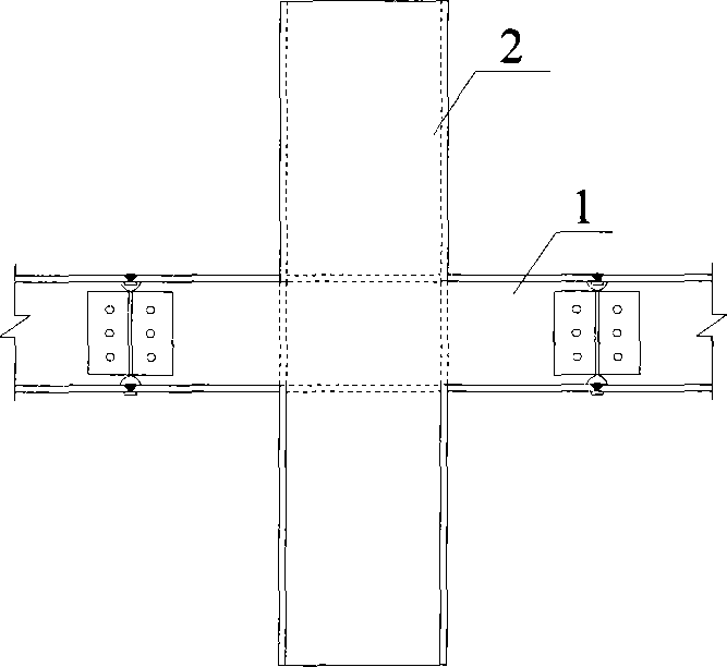
[0021] like figure 1 As shown, it is a beam-to-column connection structure at the I-beam node of a square concrete-filled steel tube column.

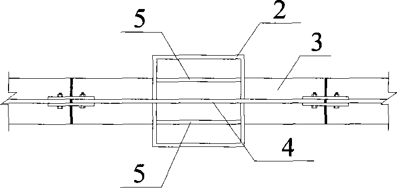
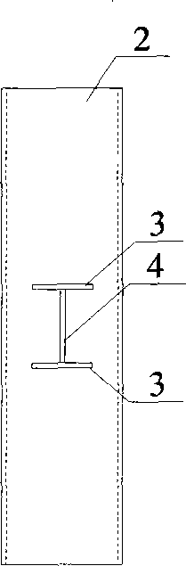
[0022] like figure 2 As shown, the web 4 of the I-shaped steel beam penetrates the wall plate of the square concrete-filled steel pipe column 2, and the internal steel plate 5 is placed vertically in the square concrete-filled steel pipe column 2, and is parallel to the web 4 of the I-shaped steel beam. The edge is flush with the flange 3 of the I-beam beam, and the edge of the inner steel plate 5 is connected with the inner...


PUM


Abstract

The present invention relates to a structure for connecting the square steel tube concrete column with the node of the axle I-beam in the construction engineering technique field, comprising a square steel tube concrete column, an axle I-beam and a built-in steel plate. The position of the axle I-beam web plate on the wallboard of the square steel tube concrete column is arranged with a vertical groove with dimension same to the girder steel web plate and the groove is taken as the channel that the axle I-beam web plate passes through the wallboard of the square steel tube concrete column. The axle I-beam web plate runs through the wallboard of the square steel tube concrete column, the wing rim of the axle I-beam is directly welded on the external wall of the square steel tube concrete column. The placing mode of the build-in steel plate in the square steel tube concrete column is vertical and is parallel with the web plate of the axle I-beam, and the edge is accordant with the wing rim of the axle I-beam. The invention increases the whole shearing resistance and bending-resisting bearing ability of the node, and guarantees the coordinate operation of the square steel tube concrete column and the axle I-beam.

Description

technical field [0001] The invention relates to a structure in the technical field of construction engineering, in particular to a node connection structure between a square steel tube concrete column and an I-shaped steel beam. Background technique [0002] At present, my country's "Technical Regulations for Rectangular Concrete-filled Steel Tube Structures" (CECS159:2004) provides steel-beam connection nodes for square concrete-filled steel tube columns mainly by inner diaphragm type and outer diaphragm type. There are following deficiencies in the connection between the square concrete-filled steel pipe column and the steel beam in the prior art: [0003] (1) The mechanical properties of joints and the simplicity and economy of construction cannot be both. In practical applications, some types of joints have better mechanical properties, and the overall stiffness of the joints is also high, but the amount of materials used is large and the construction is complicated. ...

Claims


Application Information

Patent Timeline
IPC IPC(8): E04B1/38E04B1/58
Inventor 刘明路赵金城肖斌
Owner SHANGHAI JIAO TONG UNIV
Why Eureka
Try Eureka