Equipment for cooling and heating space of building

An in-building and space technology, applied in the field of equipment used to cool and warm spaces in a building, can solve the problem of reducing large, achieve the effect of reducing noise level and simplifying batch production

Inactive Publication Date: 2008-08-13
伊日·佩特拉赫
View PDF14 Cites 2 Cited by
  • Summary
  • Abstract
  • Description
  • Claims
  • Application Information

AI Technical Summary

Problems solved by technology

It is true that the noise level does not decrease at this scale, because the reduction in noise has a logarithmic relationship, but nevertheless the reduction is quite large

Method used


Image

  • Equipment for cooling and heating space of building
  • Equipment for cooling and heating space of building
  • Equipment for cooling and heating space of building

Examples


Embodiment Construction

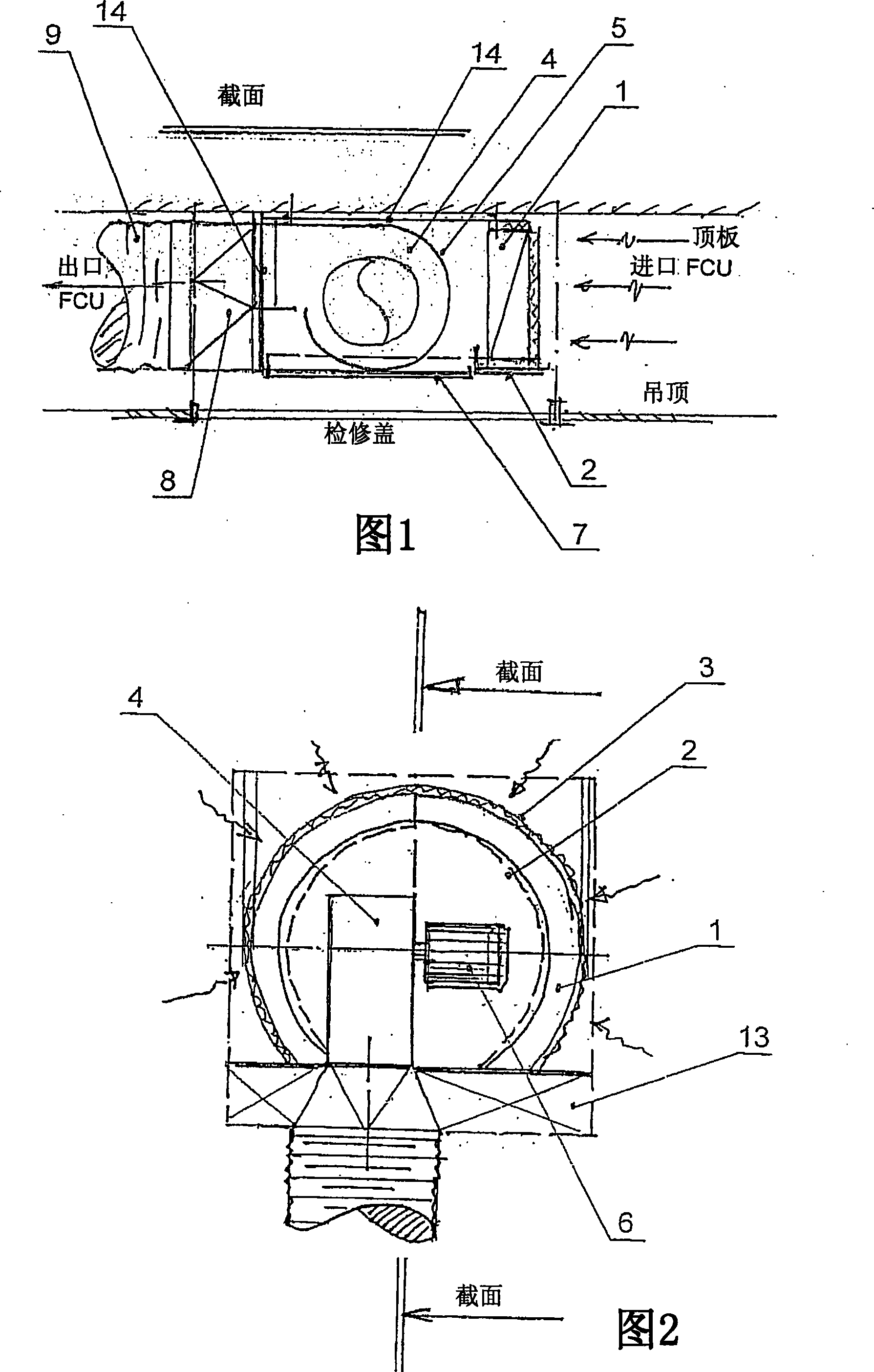
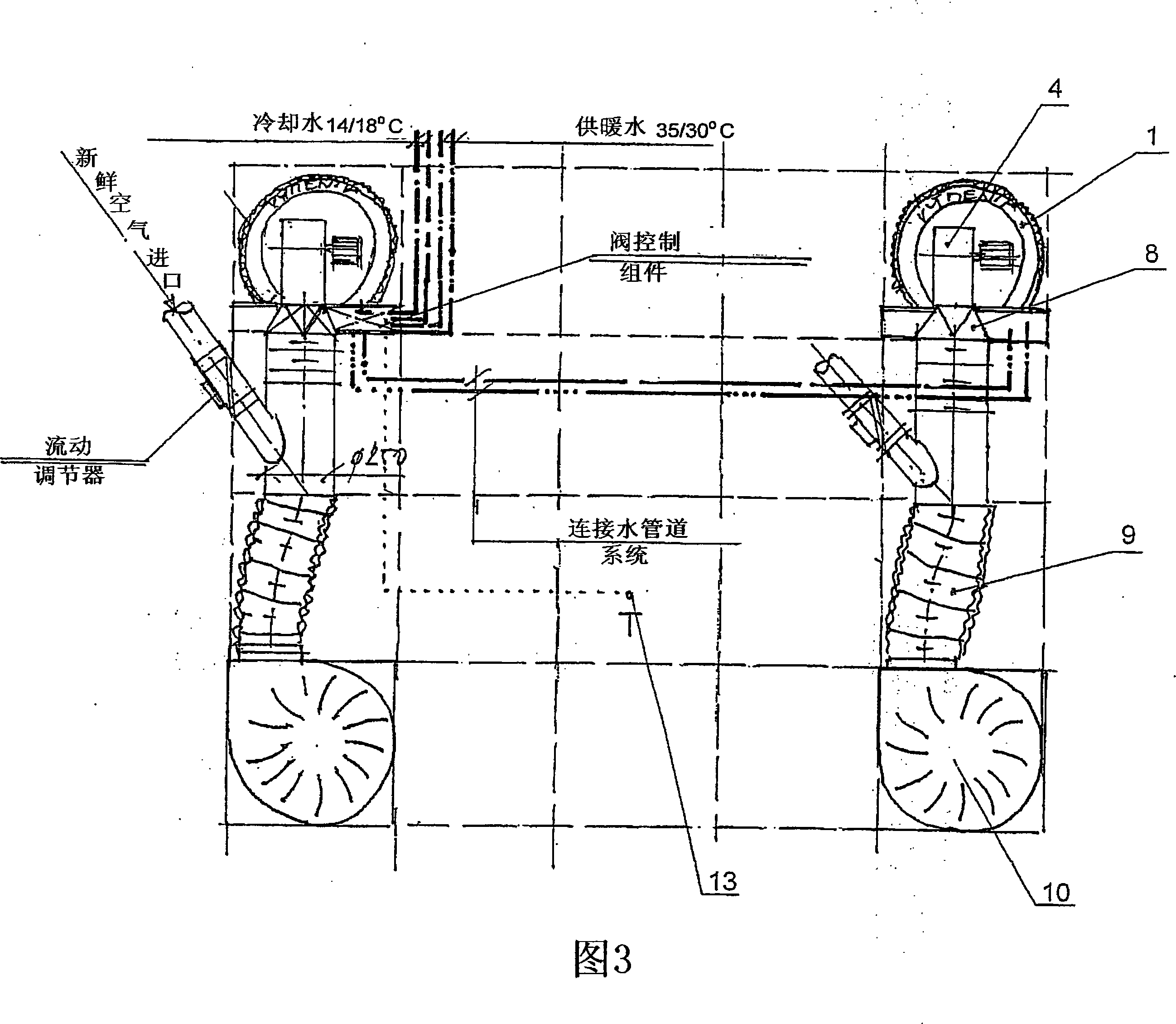
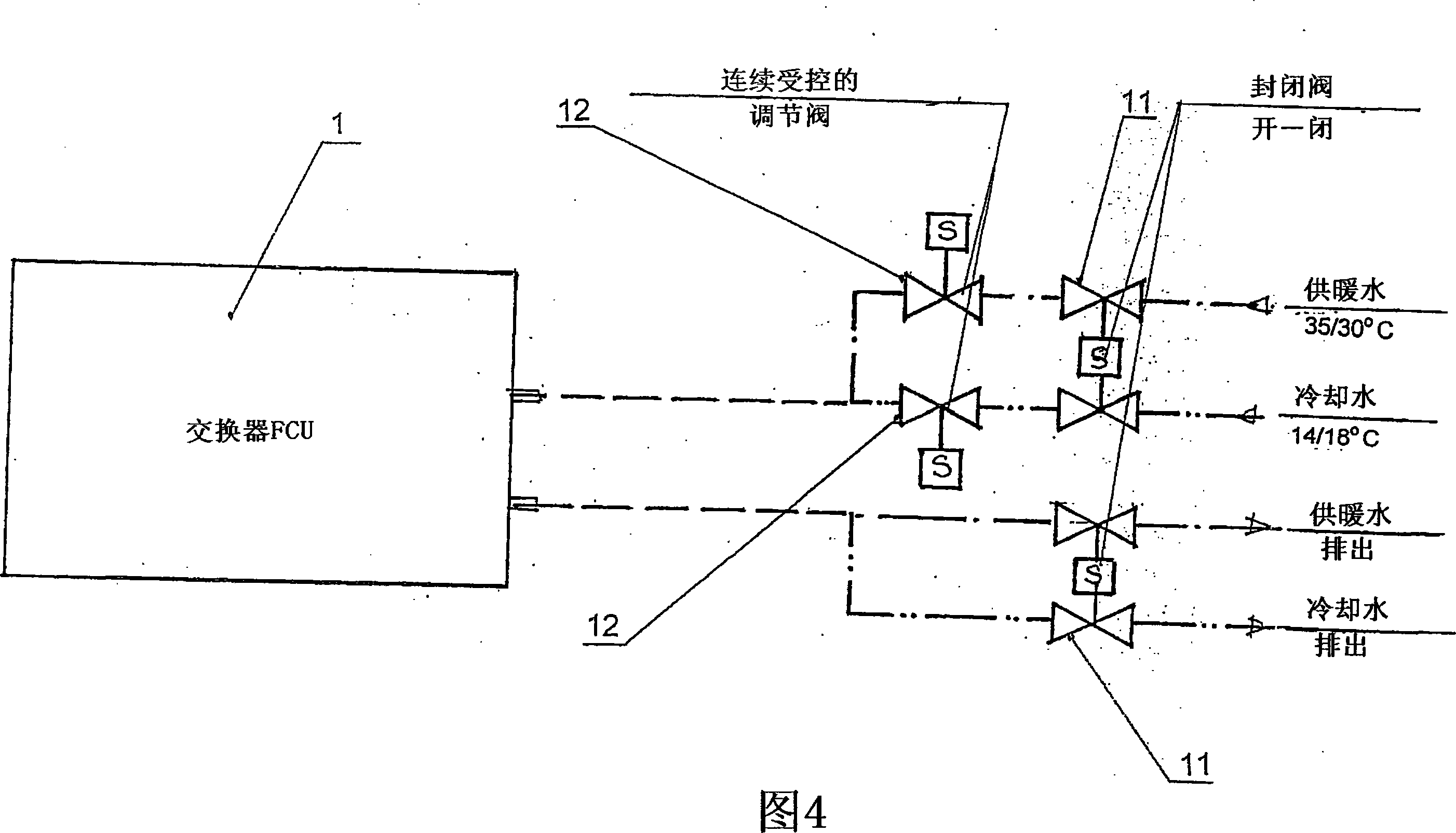
[0010] The cooling and heating plant (hereinafter referred to as the air conditioning unit) comprises a large-area multi-plate heat exchanger 1 for approximately 400m 3 / hour of airflow and about 0.2m 2 front airflow surface. The heat exchanger 1 has a height of about 220 to 250 mm and in a three-row embodiment (it can be two or four rows) comprises three rows of copper tubes with a diameter of 0.8 to 1.2 cm on which aluminum The alloy's staggered elliptical blades are arranged together in a row, which fit snugly on the surface of the copper tube. One of the banks can be used for independent connection to the heating distribution system and the remaining banks can be connected to the cooling water distribution system. The heat exchanger is arranged together with the blower 4 in the housing 14 of the air conditioning unit, which housing 14 is provided with an inlet for the circulation air and an outlet for the conditioned air. The fan 4 is located on the outlet side of the h...


PUM


Abstract

The present invention provides a device for cooling and warming space of building, in an entrance used for inlet of the circulating air and a shell used for exhaust port of the adjusted air, a heat exchanger unit having a fan, the fan is located in the exit side of the heat exchanger, a condensation jar is located in the lower of the heat transfer surface of the heat exchanger. The two ends of the heat transfer surface of the heat exchanger are tightly sealed by the shell, the shell is provided with the tightly assembled maintenance cover. The heat transfer surface of the heat exchanger is composed of a cylinder ring shaped section, the axes of the cylinder ring shaped section is vertical to the horizontal flow direction of the inlet circulating air, and the unsealed part of the cylinder is tightly assembled on the vertically sealing wall of the shell in its whole height. The cylinder heat transfer surface has an exhauster in it, the exhaust hermetically passes the vertically sealing wall of the shell in the position of the cylinder unsealing part of the heat transfer surface of the heat exchanger, connecting with an air distribution element by a distributing pipeline via an diffuser.

Description

technical field [0001] The invention relates to devices for cooling and warming spaces in buildings. Background technique [0002] In order to ensure a comfortable environment in administrative buildings, fan coil units have long been known and are used as terminal elements of air-conditioning systems in order to ensure good thermal conditions without requiring an original fresh air source. At the same time, it is introduced as a counterweight to the suction unit, trying to replace this final air-conditioning element with a sufficiently strong and flexible unit independent of the main air flow. Another purpose of its introduction was to simplify the conditioning system for warming and cooling the water, since the insertion of an auxiliary fan into the system allows a greater range of performance by circulating the air over the heat transfer surfaces. In this way, the heating and cooling performance is determined without direct dependence on the raw air source, which also me...

Claims


Application Information

Patent Timeline
Patent Type & Authority Applications(China)
IPC IPC(8): F24F3/08F24F1/0038F24F1/0047F24F1/0063
CPCF24F1/0007F28D7/02F24F13/30F24F13/24F24F2001/0037F24F1/0047F24F1/0038F24F1/0063
Inventor 伊日·佩特拉赫
Owner 伊日·佩特拉赫
Why Eureka
Try Eureka