Ratchet type rotor engine

A rotary engine, ratchet-type technology, applied in the direction of intermeshing engine, combustion engine, machine/engine, etc., can solve the problems of not being widely used and popularized, high quality requirements of parts and materials, and high requirements of machining accuracy, and it is easy to achieve. Application popularization and promotion, low processing difficulty, small friction coefficient

Inactive Publication Date: 2012-11-21
刘宏伟
View PDF0 Cites 0 Cited by
  • Summary
  • Abstract
  • Description
  • Claims
  • Application Information

AI Technical Summary

Problems solved by technology

[0002] At present, the engines commonly used in the world are all reciprocating piston engines. So far, although there are many inventions involving various forms of rotary engines, most of them have not been widely used and promoted.
The main reasons are: complex structure, low output power, poor practicability, short service life, high processing accuracy requirements, high quality requirements for component materials, and difficult sealing, etc.

Method used


Image

  • Ratchet type rotor engine
  • Ratchet type rotor engine
  • Ratchet type rotor engine

Examples


Embodiment 1

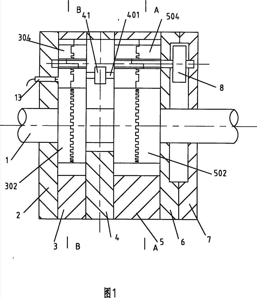
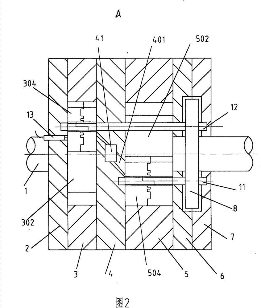
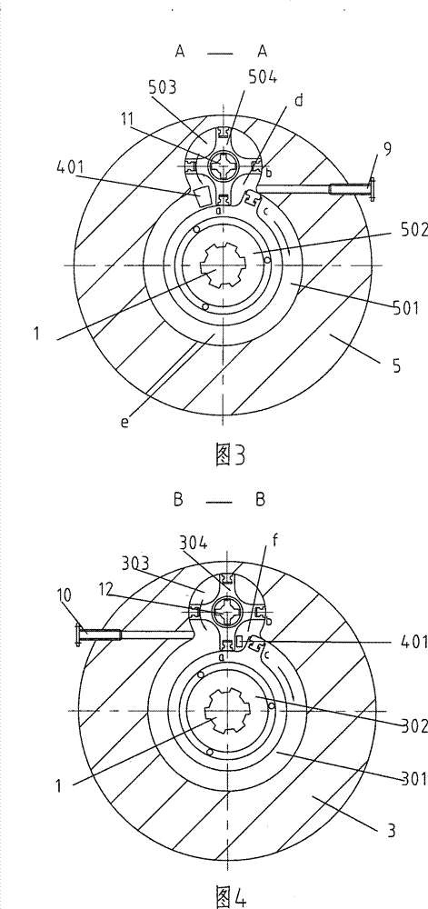
[0049] A single ratchet rotary engine such as figure 1 , 2As shown, it includes: the engine cylinder block is composed of a group of unit cylinder blocks, and each group of unit cylinder blocks is composed of a main shaft 1 and a front end cover 2 that is sealed and assembled together with each other, a power exhaust cylinder block 3, and a middle gas distribution plate 4 , the air intake compression cylinder 5, the control panel 6 and the rear end cover 7, the air intake compression cylinder 5 is provided with a circular air intake compression cylinder 501 and a ratchet intake compression ratchet rotor 502 for dynamic cooperation, The periphery of the circular intake compression cylinder 501 is connected with a circular compression auxiliary cylinder 503, and the intake compression gear ratchet 504 is arranged in the circular compression auxiliary cylinder 503. Air compression cylinder 501; a circular power exhaust cylinder 301 is arranged in the power exhaust cylinder body ...

Embodiment 2

[0078] Rotary engine with 4 ratchet sets, such as Figure 8 , 9 Shown: its structure is basically the same as that of Embodiment 1, the difference is that: the circular air intake compression cylinder 501 and the intake compression ratchet rotor 502 of 4 ratchets are dynamically matched, and the periphery of the circular intake compression cylinder 501 It is connected to four circular compression secondary cylinders 503, and an intake compression gear ratchet 504 is arranged in the circular compression secondary cylinder 503, and the circular compression secondary cylinder 503 is connected to the circular intake compression cylinder 501 through the intake compression gear ratchet 504; A circular power exhaust cylinder 301 is arranged in the power exhaust cylinder body 3, and the circular power exhaust cylinder 301 cooperates with the power exhaust ratchet rotor 302 of 4 ratchets, and the periphery of the circular power exhaust cylinder 301 is connected. 4 circular auxiliary c...


PUM


Abstract

A ratchet wheel rotor engine includes an engine cylinder and is characterized in that the engine cylinder at least consists of one group of unit cylinders. The unit cylinder consists of a round air inlet compressing cylinder and a round working exhaust cylinder. The round air inlet compressing cylinder is dynamically matched with the air inlet compressing ratchet wheel rotor with at least one ratchet. The surrounding of the round air inlet compressing cylinder is communicated with at least one vice round compressing cylinder. An air inlet compressing blocking ratchet is arranged in the vice round compressing cylinder and the vice round compressing cylinder is communicated with the round air inlet compressing cylinder through the air inlet compressing blocking ratchet wheel. The round working exhaust cylinder is dynamically matched with the working exhaust ratchet wheel rotor with at least one ratchet. The surrounding of the round working exhaust cylinder is communicated with at least one vice round cylinder. The vice round cylinder is communicated with the round working exhaust cylinder through a round working exhaust blocking ratchet wheel. The air inlet compressing ratchet wheelrotor and the working exhaust ratchet wheel rotor are respectively connected with a main shaft. The round air inlet compressing cylinder is communicated with the vice round cylinder by a valve actuating mechanism. The ratchet wheel rotor engine has the advantages of light weight, small volume and large power.

Description

technical field [0001] The invention relates to a rotary engine, in particular to a ratchet type rotary engine. Background technique [0002] At present, the engines commonly used in the world are all reciprocating piston engines. So far, although many inventions relate to various forms of rotary engines, most of them have not been widely used and promoted. The main reasons are: complex structure, low output power, poor practicability, short service life, high processing precision requirements, high quality requirements for component materials, and difficult sealing. Contents of the invention [0003] The purpose of the present invention is: in order to overcome above-mentioned deficiency of reciprocating piston engine and current rotor engine, provide a kind of ratchet type rotor engine, its whole machine does not have reciprocating mechanism, does not have linear motion, and all motion mechanisms are rotary motions, reach The structure is simple, the design is reasonabl...

Claims


Application Information

Patent Timeline
Patent Type & Authority Patents(China)
IPC IPC(8): F02B53/02F02B55/08F02B53/08F02B55/14F02B53/04
CPCF02B53/08Y02T10/17F02B55/08F02B53/02F01C1/20F02B55/14Y02T10/12
Inventor 刘宏伟
Owner 刘宏伟
Why Eureka
Try Eureka