
Activation code path detecting method for multi-antenna association detecting system

A technology of activating the code channel and joint detection, which is applied in the field of communication, can solve the problems of small antenna spacing, complex detection algorithm, small diversity gain, etc., and achieve the effect of ensuring smooth transition and high diversity gain

Inactive Publication Date: 2008-08-20
ST ERICSSON SEMICON BEIJING
View PDF0 Cites 9 Cited by
  • Summary
  • Abstract
  • Description
  • Claims
  • Application Information

AI Technical Summary

Problems solved by technology

[0003] Existing multi-antenna systems are generally combined with space-time coding and other multiple-input multiple-output (MIMO) technologies to perform space-time joint detection. Diversity gain and coding gain can be obtained in space, but the detection algorithms are relatively complicated.
In the TD-SCDMA system, the base station uses a smart antenna, which can achieve diversity reception in system implementation, but at this time the distance between the antennas is relatively small (two adjacent antennas are generally 1 / 2 wavelength), and the correlation between the antennas is relatively small. Strong, multi-antenna signals are combined and received at the receiving end, and the diversity gain obtained by completely independent multi-antenna diversity is much smaller. Moreover, the number of smart antenna elements is generally greater than or equal to 4. As the number of antennas increases, the complexity Geometric growth, which undoubtedly increases the difficulty of system implementation

Method used


Image

  • Activation code path detecting method for multi-antenna association detecting system
  • Activation code path detecting method for multi-antenna association detecting system
  • Activation code path detecting method for multi-antenna association detecting system

Examples


Embodiment Construction

[0017] In order to make the object, technical solution and advantages of the present invention clearer, the present invention will be described in detail below with reference to the accompanying drawings and specific embodiments.

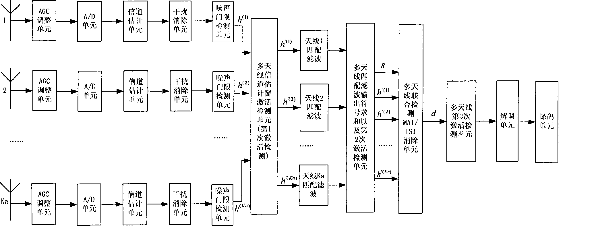
[0018] Such as figure 1 As shown, the signals enter the receiving end of the antenna through different wireless channels. In the receiving diversity system, the signals of different antennas are respectively processed by the automatic gain control (AGC) adjustment unit and the analog-to-digital (A / D) conversion unit to obtain the baseband digital signal; each baseband digital signal is sequentially processed by the channel estimation unit, interference cancellation unit and noise threshold detection unit, and the obtained channel estimation enters the multi-antenna joint activation detection process, so that the irrelevance of multi-antenna channel estimation can be fully utilized , which plays a very good role in suppressing the fading characterist...


PUM


Abstract

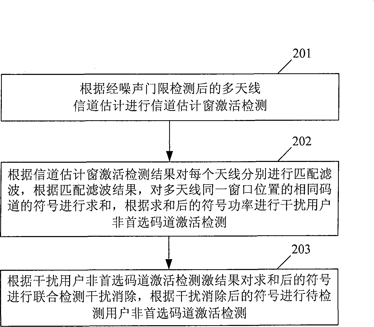
The present invention discloses an activation code channel detecting method which is applied on the multiple-antenna combined-detecting system, and the method comprises the following steps: A. executing channel estimating window activating detection according to the multiple-antenna channel estimation after the noise threshold detection; B. executing matched filtering respectively to each antenna according to the activation detecting result of the channel estimating window, summating the symbol of same code channel of multiple-antenna at a same window position according to the result of matched filtering, and executing interference-user non-preferred code channel activation detecting according to the summated symbols; and C. executing combined detection interference eliminating to the summated symbols according to the activation detecting result of the interference-user non-preferred code channel, and executing non-preferred code channel activation detection to the symbol executed with interference elimination. The method according to the invention leads to the reducing of the demodulating threshold at the state of no increasing the band width thereby increasing the system throughout, and at the same time the coverage of the service can be increased.

Description

technical field [0001] The invention relates to a multi-antenna joint detection technology in the communication field, in particular to an active code channel detection method applied to a multi-antenna joint detection system. Background technique [0002] Multi-antenna technology can effectively resist the fading of the wireless channel and improve the channel capacity of the wireless channel, and it has attracted more and more attention in the communication system. Compared with the single-antenna system, multi-antenna technology is used at the receiving end to combine the signals received on each antenna to obtain multi-antenna diversity gain and reduce the power requirement for each antenna. In the Time Division Synchronous Code Division Multiple Access (TD-SCDMA) system, the terminal adopts the multi-antenna joint detection algorithm. For high-speed services such as High-speed Packet Access (HSPA), it can improve the service throughput and reduce the demodulation thresh...

Claims


Application Information

Patent Timeline
IPC IPC(8): H04B7/04H04L1/06
Inventor 褚红发
Owner ST ERICSSON SEMICON BEIJING
Learn More