
Roller device of cold calender

A roll device, cold rolling mill technology, applied in the direction of roll, counter pressure device, metal rolling stand, etc., can solve the problems of high price, long manufacturing cycle, difficult processing, etc., to improve stability, improve reliability, Create convenient effects

Inactive Publication Date: 2008-08-27
WUXI WUYE METAL ROLLING
View PDF0 Cites 13 Cited by
  • Summary
  • Abstract
  • Description
  • Claims
  • Application Information

AI Technical Summary

Problems solved by technology

[0002] At present, the traditional HC six-high cold rolling mill generally adopts six rolls arranged vertically, and the two intermediate rolls can move in opposite directions in the axial direction. Because the intermediate rolls need to move axially, they are generally driven by work rolls. The roll must transmit the rolling torque, and the minimum diameter of the work roll must reach about 30% of the strip width. It is quite difficult to roll an extremely thin strip without intermediate annealing
At the same time, to realize the axial movement of the intermediate roller, it is necessary to use expensive displacement sensors, servo control systems and quite complicated mechanical devices, which require high precision of machined parts, difficult processing, long manufacturing cycle and high production cost.

Method used


Image

  • Roller device of cold calender
  • Roller device of cold calender
  • Roller device of cold calender

Examples


Embodiment Construction

[0013] Below the present invention will be further described in conjunction with the embodiment in the accompanying drawing:

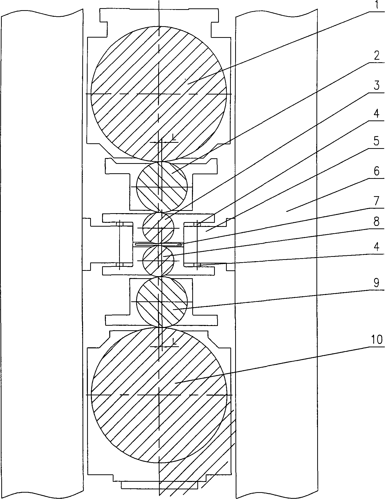
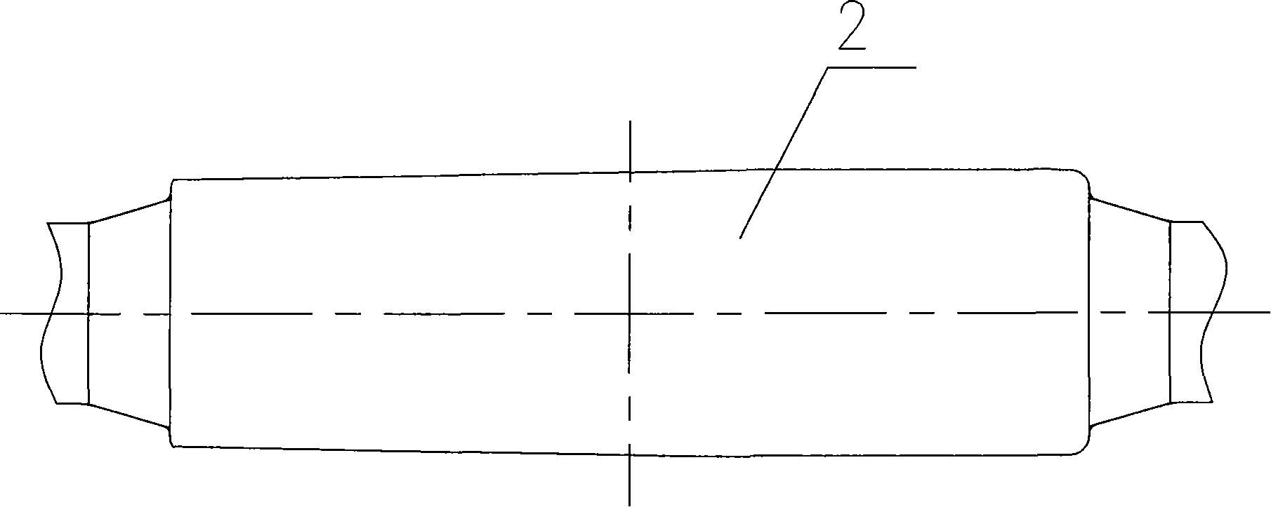
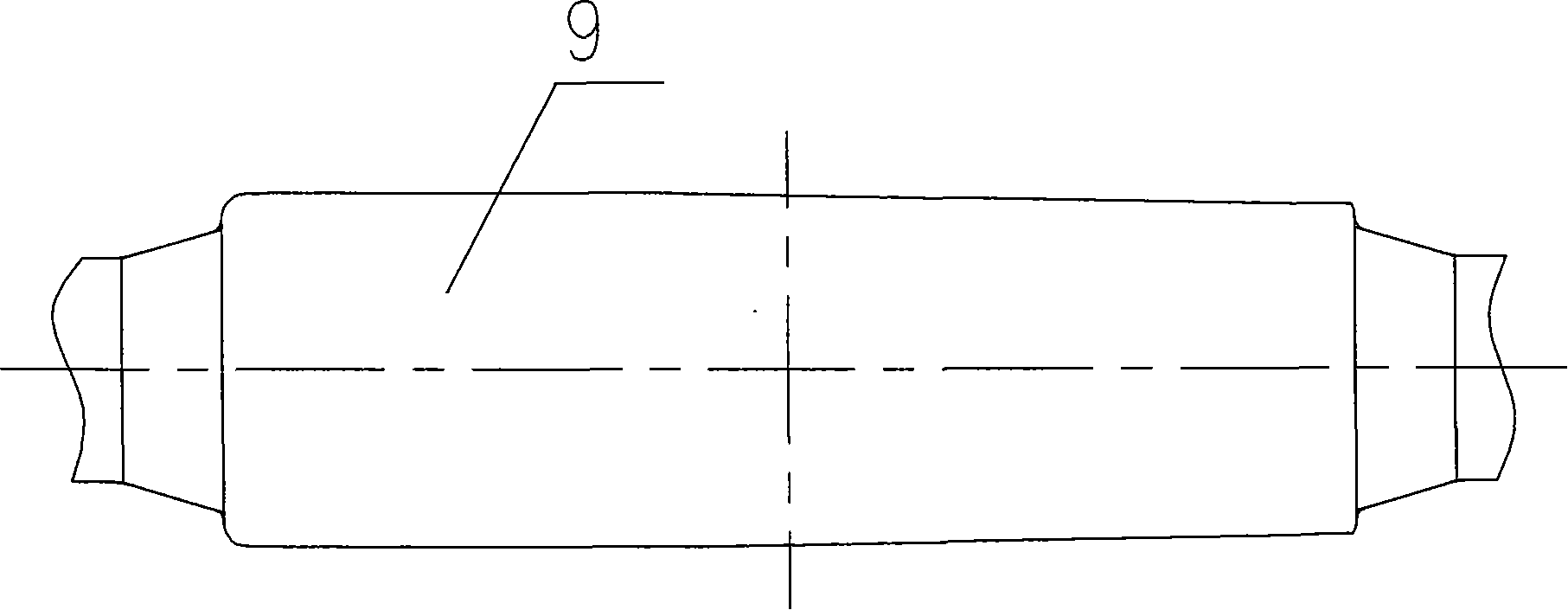
[0014] The present invention mainly consists of upper backup roll 1, upper intermediate roll 2, upper work roll 3, bending roll hydraulic cylinder 4, bending roll cylinder block 5, frame 6, strip 7, lower working roll 8, lower intermediate roll 9 and lower Support roller 10 etc. are made up. The present invention mainly adopts that the upper back-up roll 1, the upper work roll 3, the lower work roll 8, and the lower back-up roll 10 are arranged in the same vertical plane, and the upper intermediate roll 2 and the lower intermediate roll 9 are arranged in the first rolling process biased to the strip 7. In another vertical plane in the opposite direction of the forward direction; the upper intermediate roll 2 and the lower intermediate roll 9 are offset relative to the upper backup roll 1, the upper work roll 3, the lower work roll 8 and the lower backu...


PUM


Abstract

The invention relates to a rolling device of cold rolling mill, which mainly comprises an upper support roller, an upper work roller, a lower work roller and a lower support roller, which are arranged in a same vertical plane, and an upper middle roller and a lower middle roller which are arranged in another vertical plane leaning to a direction opposite to the advancing direction of a first rolling length of a strip material. The rolling device is characterized in that the upper middle roller and the lower middle roller are arranged offset with respect to the upper support roller, the upper work roller, the lower work roller and the lower support roller. The surface portions of the upper middle roller and the lower middle roller are symmetrically fabricated to form a certain conical degree. The rolling device has the advantages of simple, compact and reasonable structure; convenient manufacture and improved reliability of the rolling mill due to no axial movement of the upper and the lower middle rollers; improved stability of the rolling mill due to the offset arrangement of the upper and the lower middle rollers with respect to the support rollers and the work rollers; and reduced diameter of the work rollers by adopting the middle rolls for transmission, so that the rolling device can roll ultrathin strip materials in the case of constant rolling force.

Description

technical field [0001] The invention relates to a roll device of a cold rolling mill, in particular to a roll device on a working stand of a six-high strip cold rolling mill. Background technique [0002] At present, the traditional HC six-high cold rolling mill generally adopts six rolls arranged vertically, and the two intermediate rolls can move in opposite directions in the axial direction. Because the intermediate rolls need to move axially, they are generally driven by work rolls. The roll must transmit the rolling torque, and the minimum diameter of the work roll must reach about 30% of the strip width. It is quite difficult to roll an extremely thin strip without intermediate annealing. At the same time, in order to realize the axial movement of the intermediate roller, expensive displacement sensors, servo control systems and rather complicated mechanical devices are used, which require high precision of machined parts, difficult processing, long manufacturing cycle...

Claims


Application Information

Patent Timeline
Patent Type & Authority Applications(China)
IPC IPC(8): B21B13/02B21B13/14B21B29/00B21B27/02B21B31/32
Inventor 周小芳肖进强
Owner WUXI WUYE METAL ROLLING
Learn More