Realizing multi-attenuation band ultra-wideband aerial based on two stage type step electric impedance resonator

An ultra-wideband antenna and stepped impedance technology, which is applied in the field of comprehensive design of ultra-wideband antennas to achieve the effect of simple and fast design process, miniaturized design and small size

Inactive Publication Date: 2008-08-27
SOUTHEAST UNIV
View PDF0 Cites 11 Cited by
  • Summary
  • Abstract
  • Description
  • Claims
  • Application Information

AI Technical Summary

Problems solved by technology

The filter is composed of two two-stage ladder impedance resonators coupled with the antenna feeder

Method used


Image

  • Realizing multi-attenuation band ultra-wideband aerial based on two stage type step electric impedance resonator
  • Realizing multi-attenuation band ultra-wideband aerial based on two stage type step electric impedance resonator
  • Realizing multi-attenuation band ultra-wideband aerial based on two stage type step electric impedance resonator

Examples


Embodiment 1

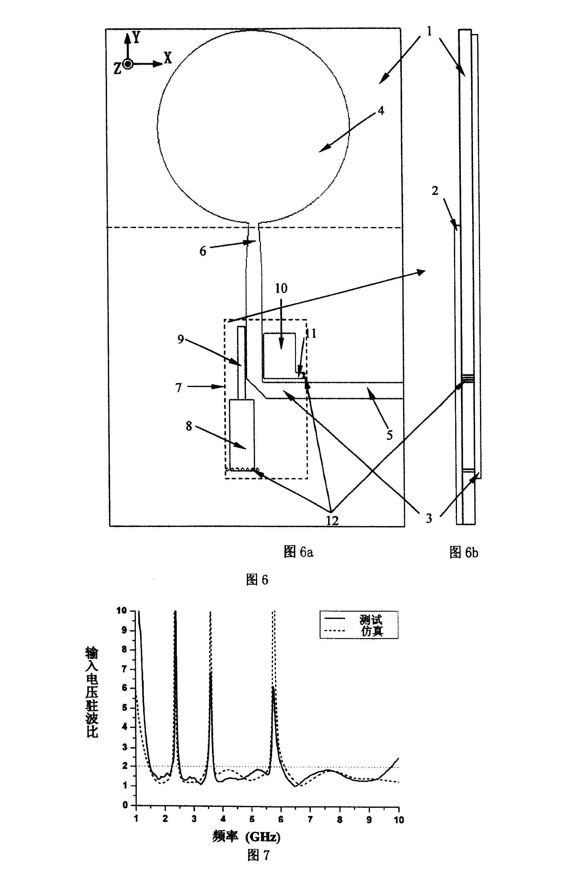
[0025] The structures of the implementation examples 1 and 2 are basically the same, only the size of the two-stage stepped impedance resonator 7b is slightly different; while the implementation example 3 has made the microstrip feeder 5 a straight-angle design, and the characteristics are the same as those of the implementation example 1. Different structures of the two can be selected according to needs in practical applications.

Embodiment 1

[0026] Embodiment 1 A two-stage stepped impedance resonator coupling feeder realizes a three-stop-band ultra-wideband antenna, type I.

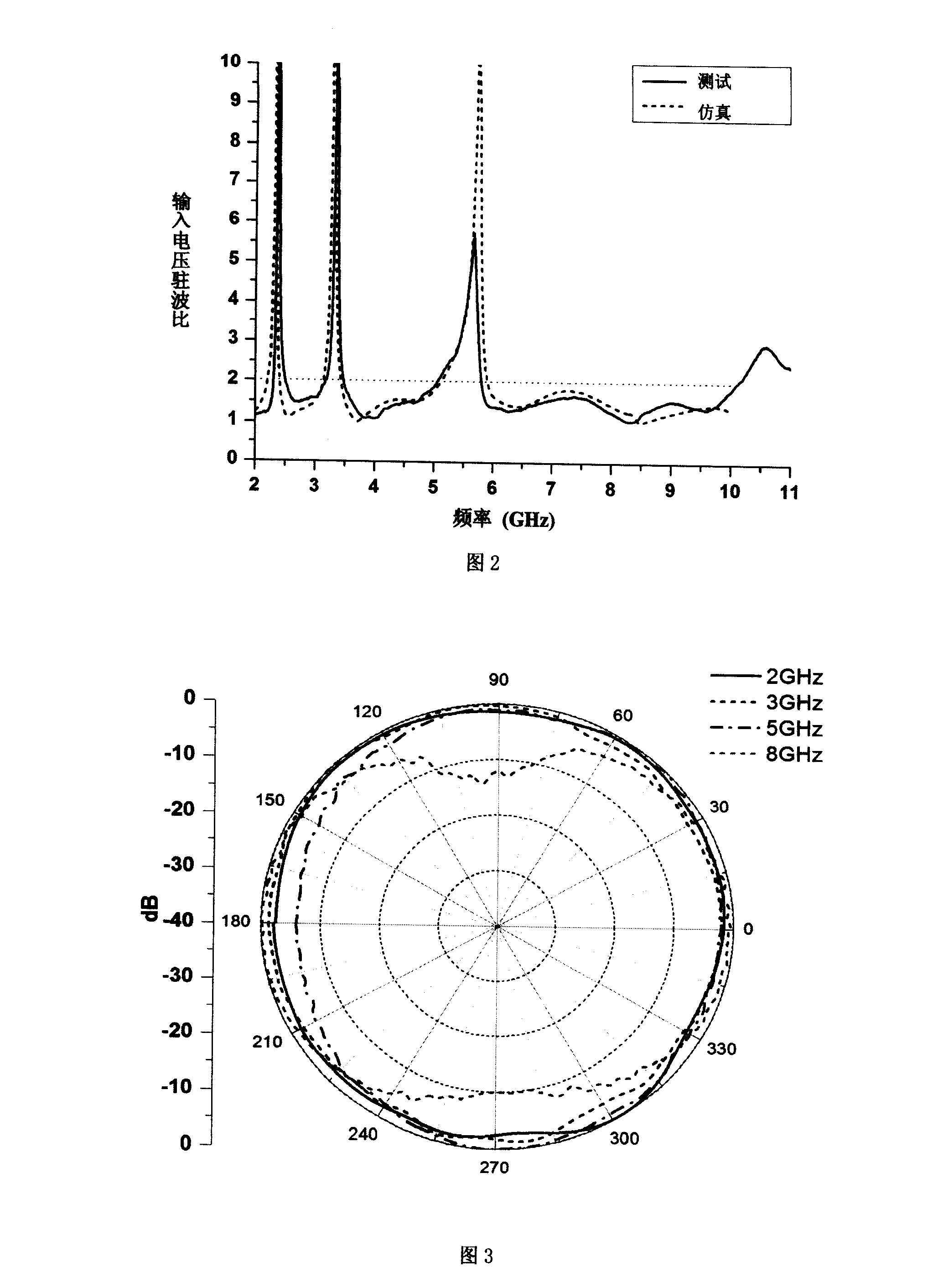
[0027] The structure of the antenna is shown in Figure 1, and the unit of size is mm. The size of the substrate in this embodiment is 46×77.5×1. The measured input voltage standing wave ratio (VSWR) and the directivity diagram results of the two main planes XOZ and YOZ are shown in Fig. 2 to Fig. 4 .

Embodiment 2

[0028] Embodiment 2 The two-stage stepped impedance resonator coupling feeder realizes the ultra-wideband antenna with four stop bands.

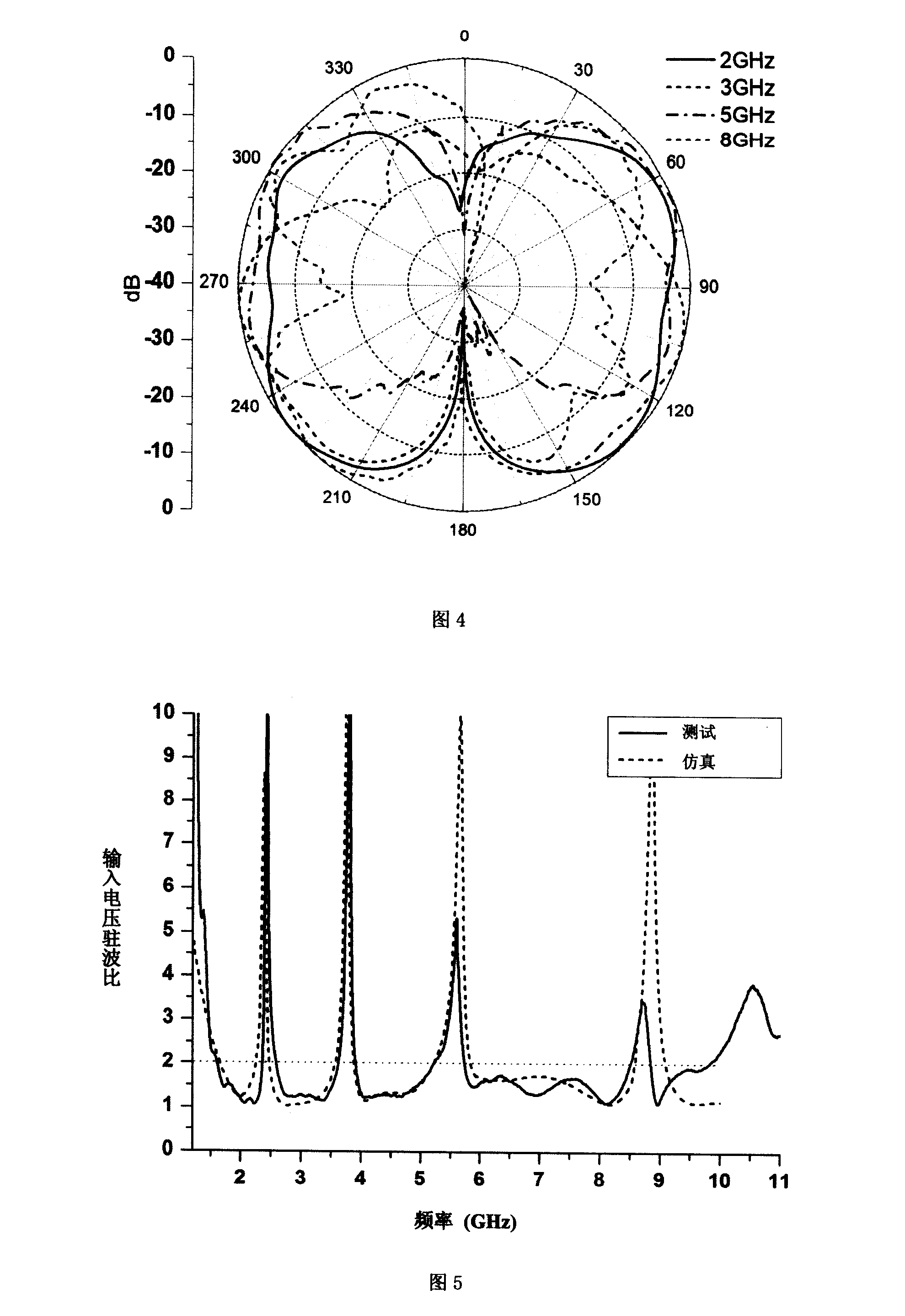
[0029] The structure of the antenna is shown in Figure 1, and the unit of size is mm. The size of the substrate in this embodiment is 46×77.5×1. The basic structure of this design example is the same as that of the implementation example 1, but it has different structural parameters of the resonator. That is, filters composed of ladder impedance resonators have different band-stop characteristics. In this example, an ultra-wideband antenna with four stopband characteristics can be realized. The measured antenna input voltage standing wave ratio (VSWR) results are shown in Figure 5.


PUM


Abstract

The invention provides a multiple stop band ultra wideband antenna which is realized based on a two-segment type ladder impedance resonator, has working characteristics of ultra wideband and can restrain the interference of multi-frequency signals; the antenna comprises a medium substrate(1) and two layers of metallic coatings which are coated on the upper and the lower surfaces of the medium substrate(1) respectively, wherein the metallic coating(2) of the lower surface is of the metallic ground of a feeder part(5), and the metallic coating(3) of the upper surface comprises an antenna radiating unit(4), a feeder(5) and a multi-band stop filter(7), wherein the antenna radiating unit(4) which is disc-shaped; no metallic ground (2) is distributed behind the disc; the radiating unit adopting the structure has ultra wideband characteristics; the feeder part(5) adopts a microstrip line form, and the multi-band stop filter(7) and a ladder-formed impedance conversion line(6) are connected between the feeder part(5) and the antenna radiating unit(4), wherein the ladder-formed impedance conversion line(6) carries out the impedance matching connection.

Description

technical field [0001] The invention is an ultra-wideband (Ultra-Wideband, UWB) antenna comprehensive design technology with ultra-wideband working characteristics and capable of suppressing multi-frequency signal interference. The designed antenna consists of a disc antenna and a coupled feeder structure with two Stepped Impedance Resonators (SIRs), and has an ultra-wideband antenna working bandwidth (1.7GHz-10.3GHz). Background technique [0002] Ultra-wideband communication system has many advantages such as high data transmission rate and low cost, and has gradually become the mainstream of indoor short-distance communication applications. However, the rapid development of various wireless communication systems today makes bandwidth resources more and more tense. It is more and more common that a large number of different communication services occupy the same frequency band. Correspondingly, since the ultra-wideband communication system occupies almost all the bandwid...

Claims


Application Information

Patent Timeline
Patent Type & Authority Applications(China)
IPC IPC(8): H01Q1/38H01Q13/08H01Q23/00H01P1/20
Inventor 洪伟张彦周健义蒯振起
Owner SOUTHEAST UNIV
Why Eureka
Try Eureka