Optic cable automatic monitoring system with optical fiber automatic switch unit

An optical fiber automatic switching and automatic monitoring technology, which is applied in the field of optical communication, can solve the problems of inconvenient monitoring and maintenance of optical cables, real-time monitoring that cannot be effectively used by the optical cable monitoring system, and differences, so as to reduce construction costs and maintenance difficulties, and achieve accurate Optical fiber fault location service, the effect of automatic switching protection

Active Publication Date: 2008-08-27
GUANGXUN SCI & TECH WUHAN
View PDF0 Cites 77 Cited by
  • Summary
  • Abstract
  • Description
  • Claims
  • Application Information

AI Technical Summary

Problems solved by technology

At present, the two systems belong to different manufacturers and have their own network management systems. They are not connected to each other, which brings inconvenience to the monitoring and maintenance of optical cables.
[0004] The existing optical cable monitoring system needs to solve two problems: 1. How to detect the abnormality of the optical cable in time; 2. How to realize the detection of the service optical fiber in use
This solution can realize the real-time monitoring of the service fiber in use, but it also has the following disadvantages: it needs to access the service fiber in use, which will cause a large number of cutover activities; It may interfere with the wavelength division system in use; the wavelength division multiplexer and optical splitter are connected to the system business, which also increases a possible hidden failure point; the launch fiber and receiving fiber of the monitored optical transmission system need to be...

Method used


Image

  • Optic cable automatic monitoring system with optical fiber automatic switch unit
  • Optic cable automatic monitoring system with optical fiber automatic switch unit
  • Optic cable automatic monitoring system with optical fiber automatic switch unit

Examples


Embodiment Construction

[0029] The specific implementation manner and working principle of the present invention will be further described below in conjunction with the accompanying drawings.

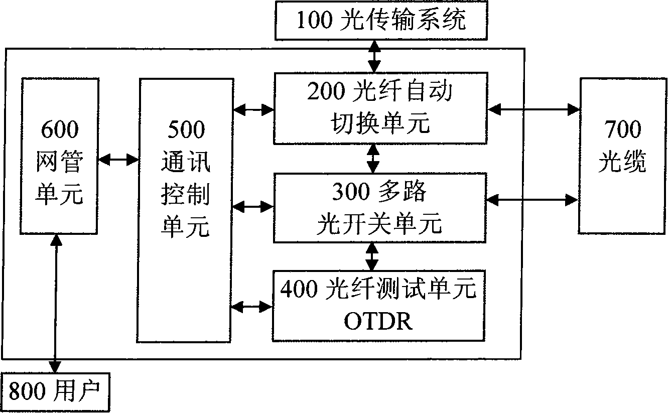
[0030] figure 1 It is a structural schematic diagram of the optical cable automatic monitoring system of the present invention. The system mainly includes: an optical fiber automatic switching unit 200 , a multi-channel optical switch unit 300 , an optical fiber testing unit (OTDR) 400 , a communication control unit 500 , and a network management unit 600 . The connection relationship between each unit is: the optical fiber automatic switching unit 200 connects the protected optical transmission system 100, the main optical cable and the backup optical cable 700 through optical fibers; the multi-channel optical switch unit 300 is connected to the redundant port of the optical fiber automatic switching unit 200 And the appropriate number of fiber cores of the main optical cable and the backup optical cable 700...


PUM


Abstract

The invention discloses an optical cable monitoring system which comprises an optical fiber automatic switching unit, a multiplex optical switch unit, an optical fiber testing unit, a communication control unit and a network management unit; wherein, the network management unit is directly connected with the communication control unit through the network; the optical fiber automatic switching unit, the optical fiber testing unit and the multiplex optical switch unit are connected with the communication control unit through the electrical interface form; the optical fiber automatic switching unit, the optical fiber testing unit and the multiplex optical switch unit are connected with each other through optical fiber interfaces. The optical cable monitoring system not only solves the alarm problem of the abnormal optical cable and the real-time monitoring problem of the operational business optical fiber, but also provides a protection function of the optical fiber line; the construction cost and the maintenance difficulty of the system are reduced. The optical cable monitoring system adopts the unified network management and integrates the GIS/GPS to realize the management of the optical fiber resources; the user can obtain the optical fiber fault location service which is convenient, rapid and accurate; meanwhile, the automatic switching protection of the optical transmission system is realized and the loss of the optical transmission business is avoided.

Description

technical field [0001] The invention relates to the field of optical communication, in particular to an automatic monitoring system for maintaining optical fiber lines and optical cables. Background technique [0002] With the development of optical fiber communication technology and the continuous expansion of optical fiber communication networks, the maintenance of optical fiber cables is becoming more and more urgent. It is very important to implement real-time protection and monitoring of optical cable lines. [0003] The optical cable automatic monitoring system uses the optical time domain reflectometer (OTDR) to realize the automatic monitoring of the optical cable line and locate the fault point of the optical fiber by testing the backscattering curve of the optical fiber. Real-time monitoring and maintenance of optical cables can be realized through this system. At present, the protection of optical fiber lines is mainly realized through the automatic switching pro...

Claims


Application Information

Patent Timeline
IPC IPC(8): H04B10/08H04B10/12H04B10/032H04B10/075
Inventor 胡强高喻杰奎周治柱彭明泉罗清杨睿夏晓文
Owner GUANGXUN SCI & TECH WUHAN
Why Eureka
Try Eureka