
Plat type heat transfer machine

A thermal transfer machine, flat-bed technology, applied in rotary printing machines, printing machines, transfer printing, etc., can solve the problems that the transfer paper cannot be uniformly thermally transferred, cannot be quickly thermally transferred, and has poor results. Achieve uniform heat transfer effect

Inactive Publication Date: 2008-09-03
崔昌植
View PDF0 Cites 3 Cited by
  • Summary
  • Abstract
  • Description
  • Claims
  • Application Information

AI Technical Summary

Problems solved by technology

In addition to the central part of the periphery, the transfer paper cannot be thermally transferred evenly, and there are some problems such as poor effect.
And in order to make the texture of the thermal transfer effect between the heat transfer plate and the base and the adhesive tape of the second transfer part attached to the transfer paper cannot cross quickly, nor can it be thermally transferred quickly

Method used


Image

  • Plat type heat transfer machine
  • Plat type heat transfer machine
  • Plat type heat transfer machine

Examples


Embodiment Construction

[0031] The present invention will be further described below in conjunction with the accompanying drawings and specific embodiments.

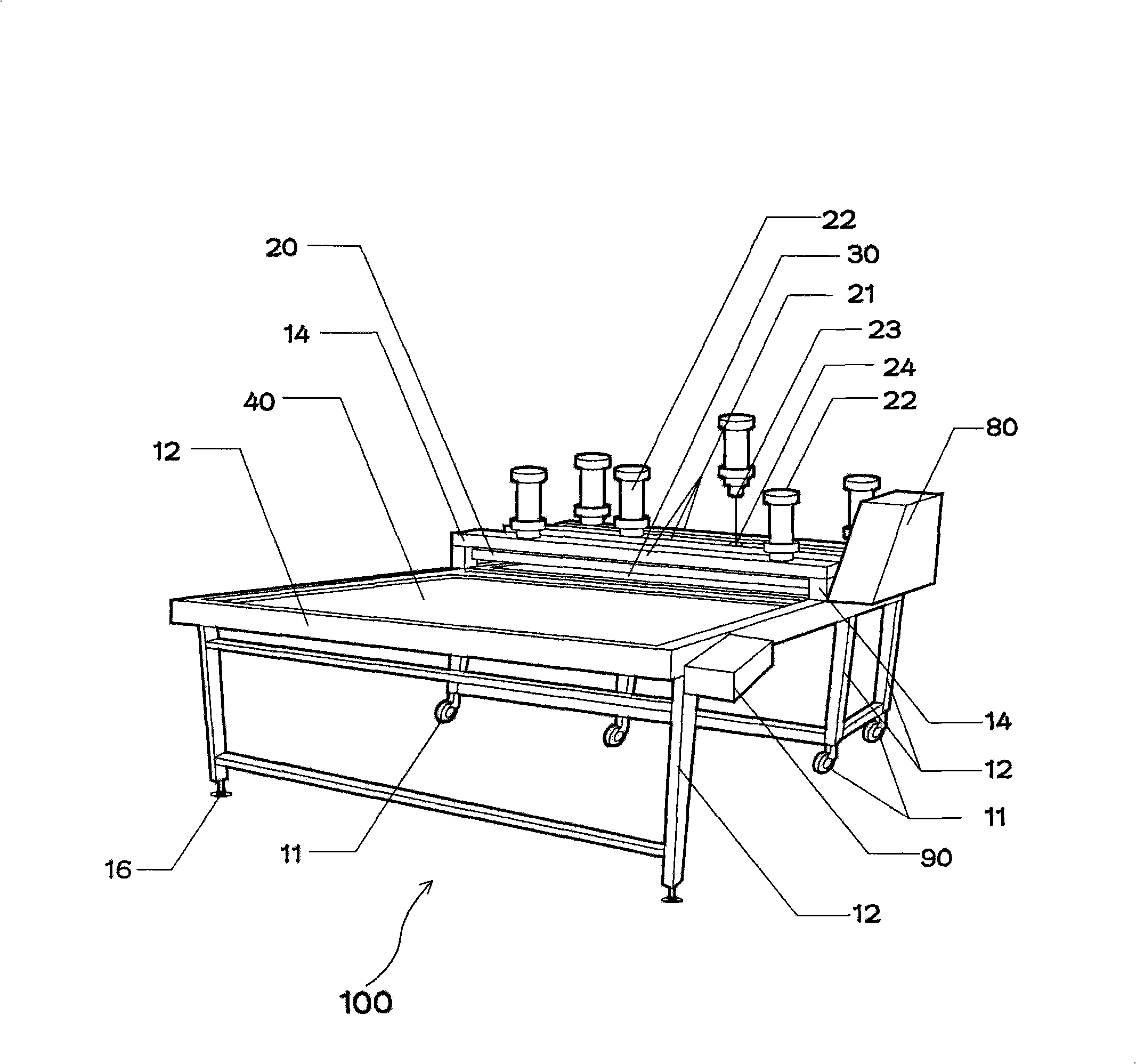
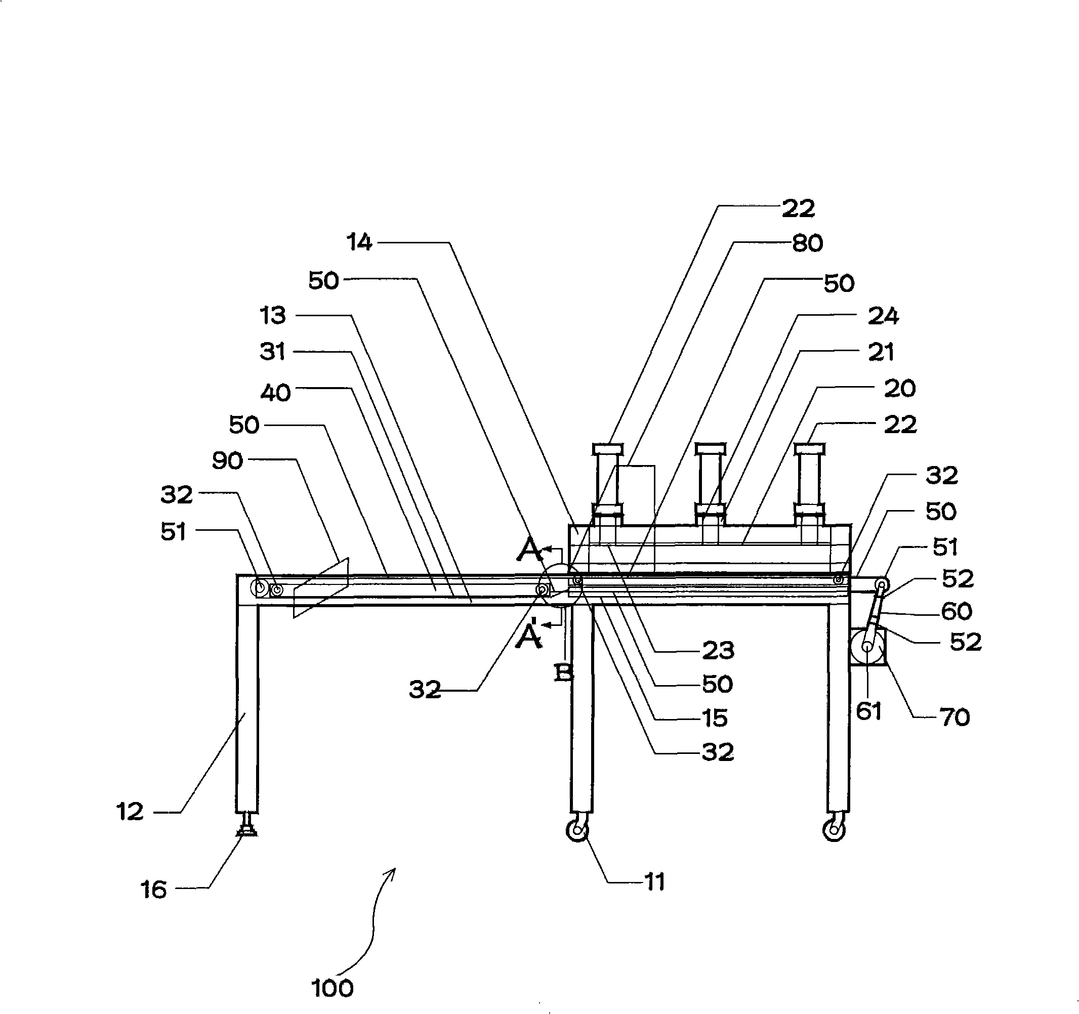
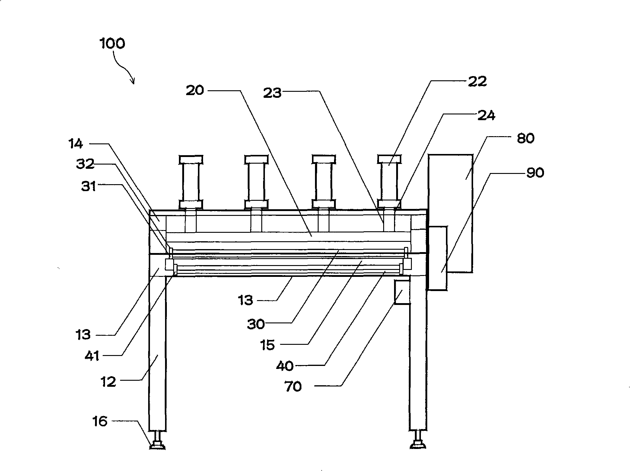
[0032] Such as Figure 1-6 As shown, the flatbed thermal transfer machine 100 consists of a body 10 and a base 15, a bracket 21, a cylinder 22, an electric heating plate 20, the first and second transfer parts 30, 40, the first and second connecting members 50, 60, and the motor 70 , The first and second control components 80,90 are composed.

[0033] The above-mentioned body 10 is composed of a frame 13 and a supporting frame 14, the upper face of the frame 13 forms a base 15, and the supporting frame is located above the rear side of the frame.

[0034] Several supports 12 are arranged below the above-mentioned frame, and the support at the front part of the above-mentioned frame 13 forms a fixed ring 16 at the bottom;

[0035] The electric heating plate 20 forms a plurality of brackets 21 at the lower part of the support frame 14 , and for...


PUM


Abstract

The invention discloses a plate type heat transfer machine, comprising a body, a first transfer portion and a second transfer portion, which are arranged on the front and rear parts of the upper and lower guide parts inside the frame of the body and move heat transfer by tapes, and an electric heating plate controlled by an air pressure cylinder, an oil pressure cylinder or an electric cylinder on a support, a plurality of cylinders controlling the lift of the electric heating plate are disposed on a plurality of pallets, the electric heating plate is evenly connected to the first and second transfer portions of a texture when heat transferring, preventing the minus effect that a transfer paper is only transferred on the edge of the texture in a current heat transfer machine using a cylinder, and having favorable effect that a transfer paper is evenly transferred.

Description

technical field [0001] The invention relates to a heat transfer machine, in particular to a flat plate heat transfer machine. Background technique [0002] Ordinary heat transfer machine is to fix the texture and the heat transfer machine on the base, make the electric heating plate rise and fall, and use the heat of the above electric heating plate to thermally transfer the transfer paper on the texture. But above-mentioned thermal transfer machine is to make the electric heating plate that the upper part of above-mentioned base lifts up and down, and the bracket that has numerous air cylinders is arranged on both sides of the upper part of electric heating plate, and above-mentioned electric heating plate is closely attached to above-mentioned base when heat transfer. The thermal transfer of printing paper is only limited to the periphery of the texture. In addition to the central part of the periphery, the transfer paper cannot be thermally transferred evenly, and there ...

Claims


Application Information

Patent Timeline
Patent Type & Authority Applications(China)
IPC IPC(8): B41F16/00
CPCB41F16/00B41F16/0093B41J2/315B41M5/00B41M5/0052
Inventor 崔昌植
Owner 崔昌植
Learn More