Knitting plating method and knitting parts used thereof

A technology for knitting components and knitting yarns, which is applied to weft knitting, circular knitting machines for weft knitting with separate action needles, knitting, etc.

Inactive Publication Date: 2008-09-03
PRECISION FUKUHARA WORKS
View PDF3 Cites 10 Cited by
  • Summary
  • Abstract
  • Description
  • Claims
  • Application Information

AI Technical Summary

Problems solved by technology

Due to the use of two yarn feeders in this way, the production volume is halved
[0007] In addition, in the prior art of knitting a plurality of knitting yarns using a double-knit knitting machine with the yarn supply switching device described in Patent Document 2, two knitting yarns are combined Yarn, but since the yarn is supplied from the same place, the yarn is easy to reverse each other, and it cannot be said to be a complete plaited weave

Method used


Image

  • Knitting plating method and knitting parts used thereof
  • Knitting plating method and knitting parts used thereof
  • Knitting plating method and knitting parts used thereof

Examples


Embodiment 1

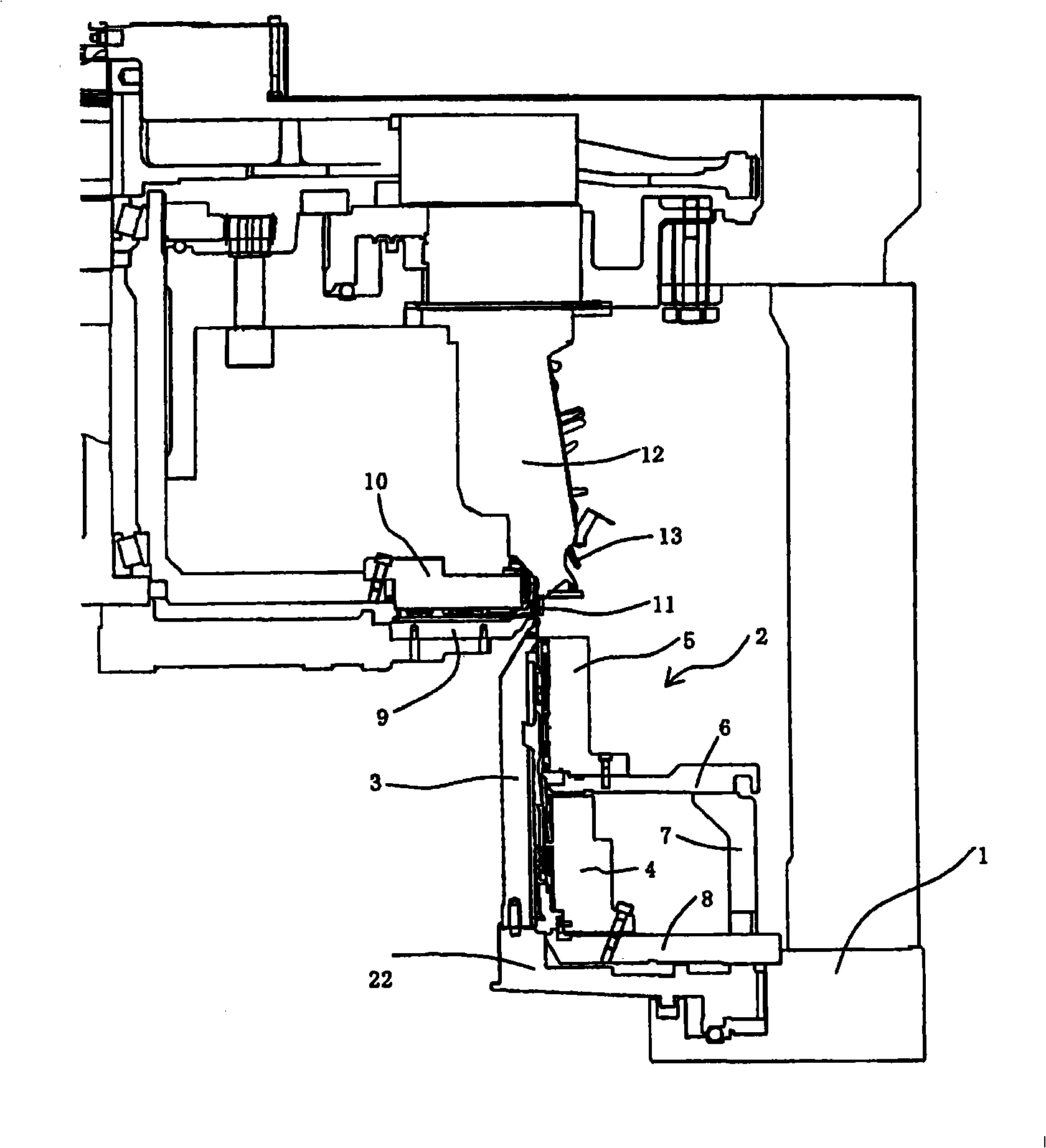
[0050] figure 1It is a sectional view showing main parts of the knitting part of the double-knit circular knitting machine. A braided portion 2 is provided above a base 1 supported by a plurality of brackets (not shown). Symbol 3 among the figure represents syringe. A cylinder needle (not shown) that is slidable in the vertical direction is housed in an upper portion of a needle groove (not shown) formed on the outer periphery of the needle cylinder 3 .

[0051] A bottom piece (not shown) for controlling the needle of the needle cylinder is housed in the lower part of the needle groove of the needle cylinder 3 . A needle selector 4 is arranged opposite to the lower part of the needle cylinder 3 to control the foot piece so as to display patterns on the fabric. A cylinder cam holder 5 for controlling the cylinder needle is arranged on the upper part of the needle selector 4, and the cylinder cam holder 5 is accommodated in the cylinder cam holder 5 to make the cylinder needl...

Embodiment 2

[0087] Figure 4 It is a cross-sectional view showing a knitting section of a single-jersey circular knitting machine, and a knitting section 2B is provided above a machine base 1B supported by a plurality of brackets (not shown). Symbol 3B in the figure represents a syringe. A cylinder needle (not shown) that is slidable in the vertical direction is housed in a needle groove (not shown) formed on the outer periphery of the needle cylinder 3B.

[0088] Needle selection is performed in the needle selector portion 4B facing the needle cylinder 3B to provide variations in the knitting structure. A cylinder cam 5B for controlling the cylinder needle is arranged on the upper part of the needle selector part 4B, and the cylinder needle is reciprocated up and down by a cam (not shown) accommodated in the cylinder cam 5B.

[0089] In addition, the cylinder cam 5B is supported by an annular intermediate ring 6B. The intermediate ring is supported by the lower ring 8B via the support...


PUM


Abstract

The invention provides a plating knitting method capable of simultaneously and reliably supplying and switching face yarn and ground yarn without reducing productivity, and a special yarn composed of the face yarn and the ground yarn are not inverted. The knitting member is a knitting member used when a selectively operated finger (13) of a striper box (12) which at least switches three knitting yarns in a circular knitting machine, supplies yarn to a needle, and is composed of a yarn carrier (11) and a yarn separation member (16). The yarn carrier (11) is provided with at least two yarn guide slots (11P). The yarn separation member (16) separates the first yarn and guides to a first guide slot (11P) of the yarn guide slots, and separates the second yarn and guides to a second guide slot (11G) of the yarn guide slots.

Description

technical field [0001] The present invention relates to a plating knitting method of a circular knitting machine with a yarn supply switching device capable of knitting switching patterns and a knitting part used therein. Background technique [0002] Regarding the plating knitting method using a single knit (single knit) knitting machine, it is generally known that in a circular knitting machine, a plurality of dissimilar yarns are combined in one yarn supply guide (yarn supply port) and fed to the weaving machine. The needle feeds the yarn, and the yarns are woven simultaneously without being reversed (see Patent Document 1 below). [0003] In addition, as a prior art for knitting a plurality of knitting yarns using a double-knitting machine equipped with a yarn supply switching device, there is a yarn supply switching device for a knitting machine filed by the present applicant (refer to Patent Document 2 below). Therein, it is described that at least one or more fingers...

Claims


Application Information

Patent Timeline
Patent Type & Authority Applications(China)
IPC IPC(8): D04B15/38D04B9/00
Inventor 中村保雄
Owner PRECISION FUKUHARA WORKS
Why Eureka
Try Eureka