Lampshade structure and backlight module
A technology of backlight module and lampshade, which is applied in the field of lampshade structure and backlight module, and can solve the problems that light-emitting diodes and light guide plates cannot be closely matched, affect display brightness and image quality, and reduce the efficiency of light transmission to liquid crystal panels, etc.
- Summary
- Abstract
- Description
- Claims
- Application Information
AI Technical Summary
Problems solved by technology
Method used
Image

Examples
no. 1 example
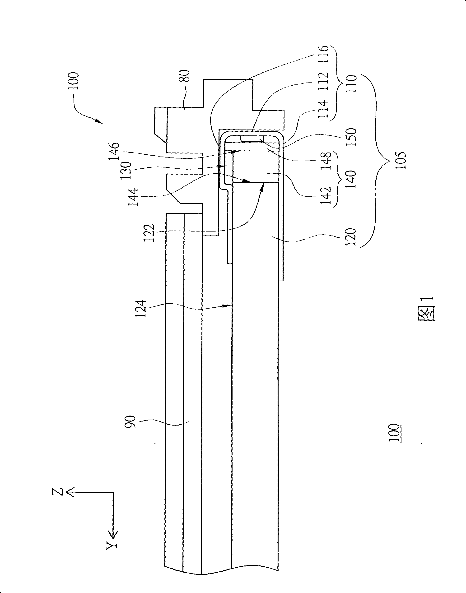
[0040] Please refer to FIG. 1 , which shows a cross-sectional view of a liquid crystal display device applying the present invention. The liquid crystal display device 100 includes a liquid crystal panel 90 and a backlight module 105 . The backlight module 105 is disposed on the back of the liquid crystal panel 90 for providing a light source to the liquid crystal panel 90 .
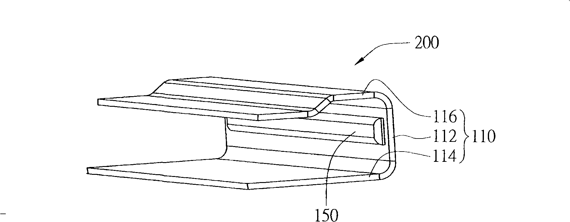
[0041] The backlight module 105 of this embodiment includes a metal component 110 , a light guide plate 120 , a light emitting component 140 and a protruding structure 150 . The metal component 110 has a base plate 112 and two side plates 114 and 116 respectively disposed on two sides of the base plate 112 , and the two side plates 114 and 116 are opposite to each other. The light guide plate 120 , the base plate 112 and the two side plates 114 and 116 enclose an accommodating space 130 .
[0042] As shown in FIG. 1 , the light emitting component 140 is disposed in the accommodating space 130 , and the...
no. 2 example
[0053] The difference between the lampshade structure of this embodiment and the above embodiment lies in the arrangement of the protrusion structure, and the same reference numerals are used for other identical components, which will not be repeated here.
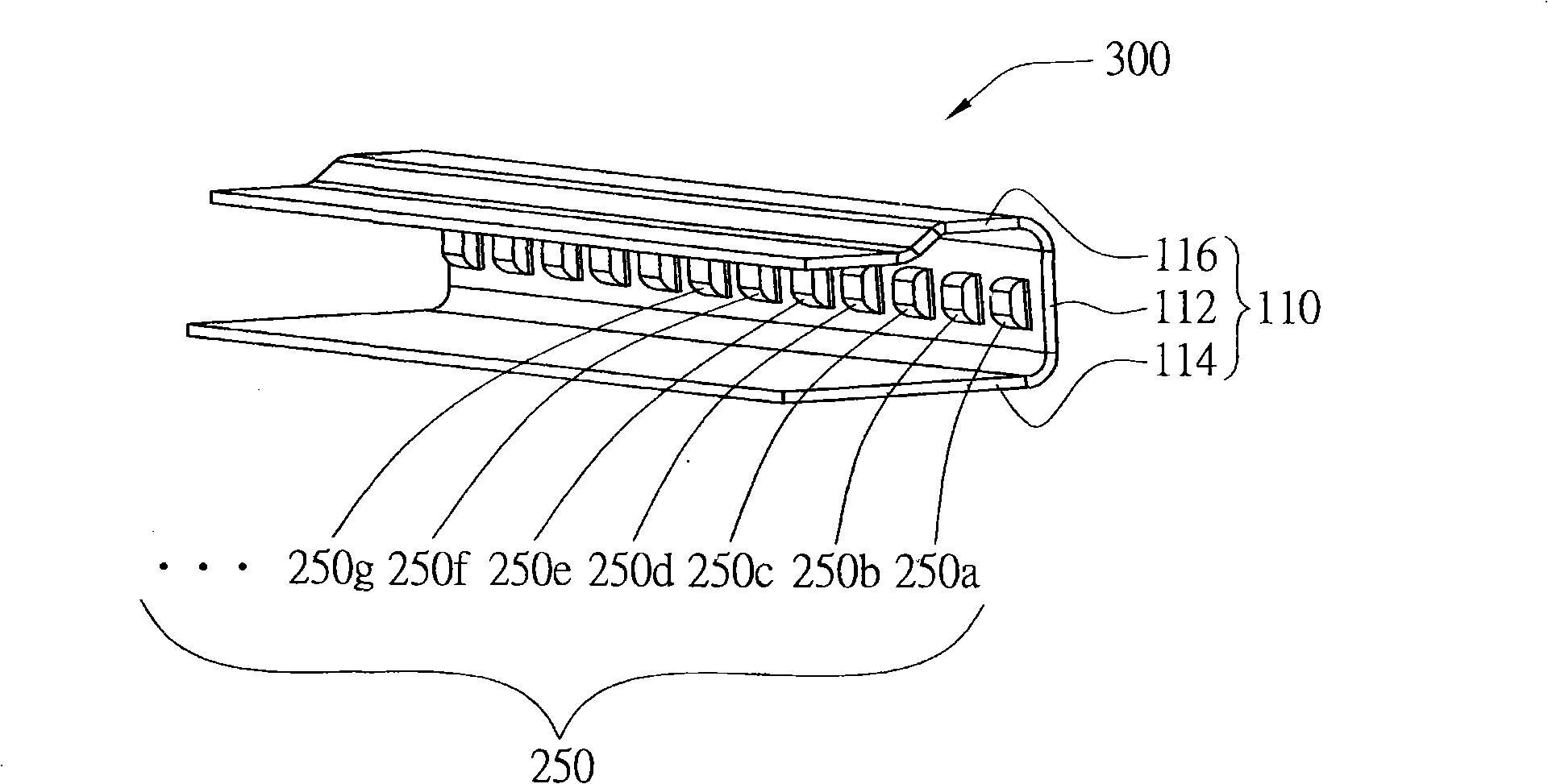
[0054] Please refer to image 3 , which shows a perspective view of the lampshade structure according to the second embodiment of the present invention. The lampshade structure 300 of this embodiment includes a metal part 110 and a protruding structure 250, the protruding structure 250 is disposed on the substrate 112 of the metal part 110, and the protruding structure 250 includes a plurality of parts 250a, 250b, 250c, 250d, 250e, 250f , 250g, ..., and these parts are provided separately from each other. The plurality of parts 250a, 250b, 250c, 250d, 250e, 250f, 250g... of the protruding structure 250, the adjacent intervals of each other can be regularly changed intervals, for example: the adjacent intervals are all the...
no. 3 example
[0056] The difference between the lampshade structure of this embodiment and the above embodiment lies in the arrangement of the protrusion structure, and the same reference numerals are used for other identical components, which will not be repeated here.
[0057] Please refer to Figure 4 , a perspective view of a lampshade structure according to a third embodiment of the present invention. The protruding structure 350 of the lampshade structure 400 of this embodiment is disposed on the base plate 112 of the metal component. It is shown that the protruding structure 350 includes a protruding portion 354 and two connecting portions 351 and 352 . The two connecting portions 351 and 352 are respectively disposed on the substrate 112 and opposite to each other, and both protrude from the substrate 112 toward the direction (i.e.+Y direction) of the light-emitting component (140 shown in FIG. 1 ). The protruding portion 354 is disposed on the two connecting portions 351 and 352 a...
PUM
 Abstract
Description
Claims
Application Information
 - R&D
- Intellectual Property
- Life Sciences
- Materials
- Tech Scout
- Unparalleled Data Quality
- Higher Quality Content
- 60% Fewer Hallucinations
Browse by: Latest US Patents, China's latest patents, Technical Efficacy Thesaurus, Application Domain, Technology Topic, Popular Technical Reports.
© 2025 PatSnap. All rights reserved.Legal|Privacy policy|Modern Slavery Act Transparency Statement|Sitemap|About US| Contact US: help@patsnap.com