Method and apparatus for testing surface defect

A defect detection and defect technology, applied in the detection field, can solve the problems of defect misjudgment, missed judgment, low detection accuracy, unfavorable labor saving, etc., to achieve the effect of avoiding misjudgment and improving detection efficiency

Inactive Publication Date: 2008-09-03
INST OF IND TECH GUANGZHOU & CHINESE ACADEMY OF SCI +1
View PDF0 Cites 46 Cited by
  • Summary
  • Abstract
  • Description
  • Claims
  • Application Information

AI Technical Summary

Problems solved by technology

[0003] First of all, the work efficiency of applying this method is very low, which is not conducive to saving labor force and improving production efficiency
[0004] Secondly, due to human factors, es

Method used


Image

  • Method and apparatus for testing surface defect
  • Method and apparatus for testing surface defect
  • Method and apparatus for testing surface defect

Examples


Embodiment 1

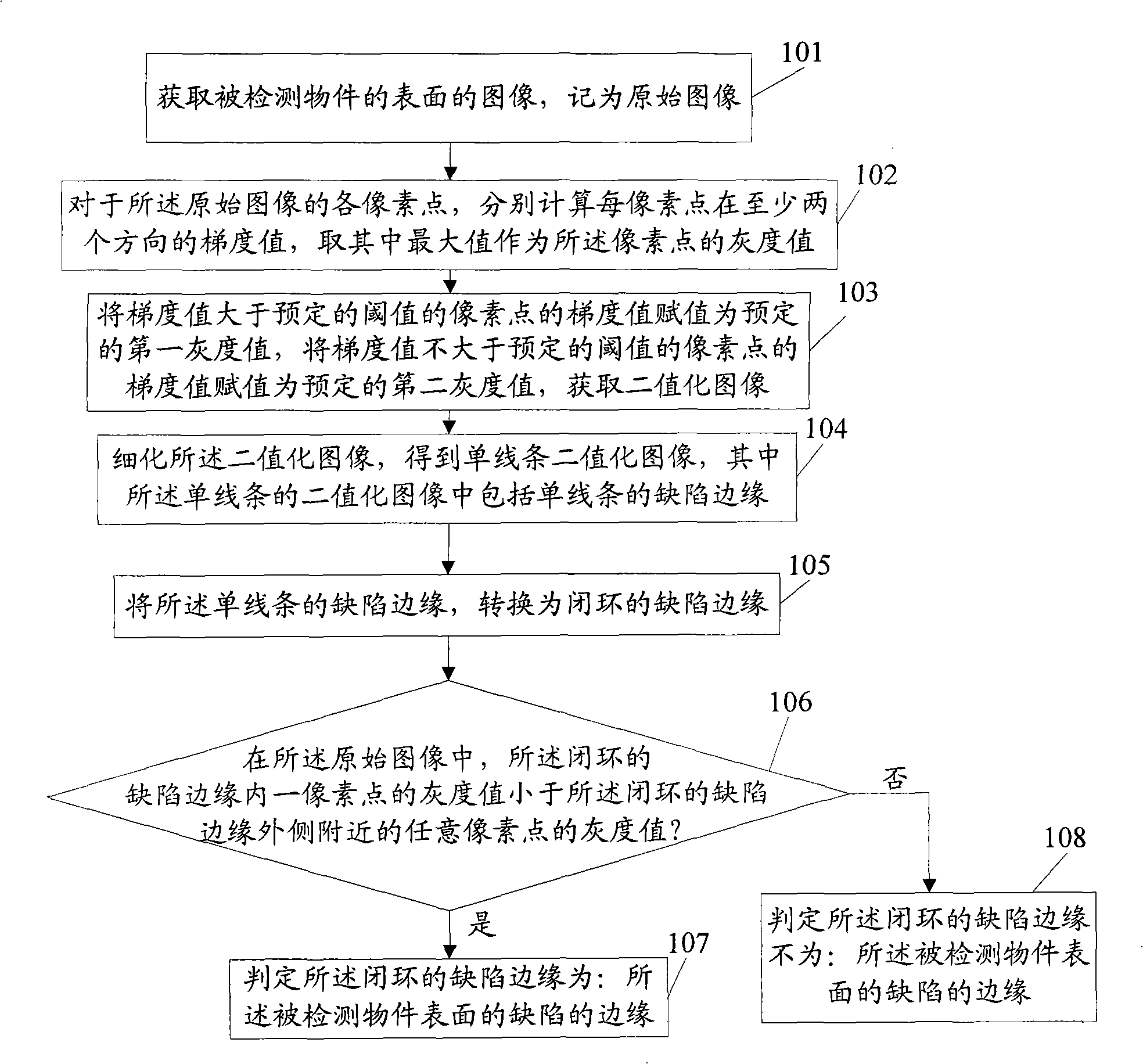
[0032] figure 1 It is a schematic flow chart of the surface defect detection method of this embodiment, as shown in the figure, the method includes:

[0033] Step 101: Obtain an image of the surface of the detected object, which is recorded as an original image.

[0034] Use the existing optical imaging equipment (such as video camera, camera, etc.) to obtain the optical image of the detected object, which is recorded as the original image, expressed as F(x, y), and the gray value of each pixel is recorded as: f(x, y), where x and y are the abscissa and ordinate of the pixel point respectively, the value range of x is 0 to ImagWidth, and the value range of y is 0 to ImagHeight.

[0035] For optical imaging, the gray value of a certain pixel on the image is larger because the point reflects more light to the camera, which is reflected on the surface of the detected object, so the point is relatively smooth, so the image of the detected object The change of the gray value can ...

Embodiment 2

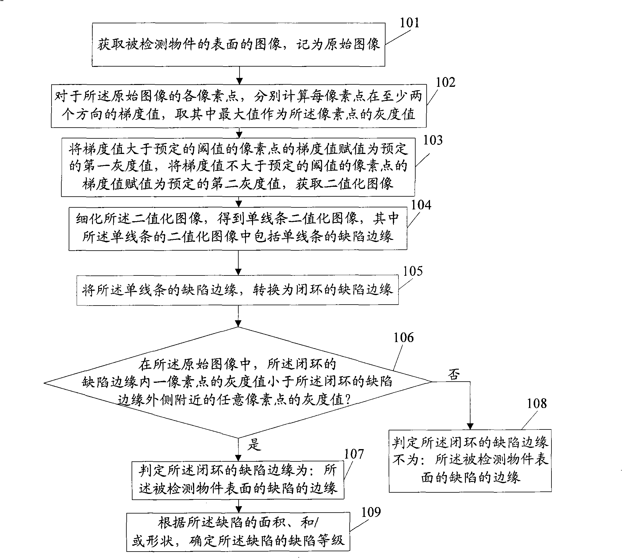
[0068] Figure 4 The schematic flow chart of the surface defect detection method provided in this embodiment, as shown in the figure, the difference between the method of this embodiment and the method of Embodiment 1 is that the method further includes step 109 after step 107 .

[0069] Step 109: Determine the defect level of the defect according to the area and / or shape of the defect.

[0070] Generally, in the process of industrial inspection, after the defect is detected, the defect can also be divided, and the defect can be processed accordingly according to the division, so after step 106, this step can also be performed:

[0071] After a defect is found, determine whether the defect is a point defect, a line defect, or a surface defect according to the shape of the defect (the shape of the edge of the defect in a closed loop), and / or to perform corresponding processing according to the defect level.

Embodiment 3

[0073] Figure 5 It is a schematic structural diagram of the surface defect detection device of this embodiment, as shown in the figure, the device includes:

[0074] The input unit 501 is used to input the image of the surface of the detected object, which is recorded as the original image.

[0075] For specific principles, refer to the description of step 101 in the embodiment.

[0076] The gradient image determination unit 502 is used to calculate the gradient values ​​of each pixel in at least two directions for each pixel of the original image, and take the maximum value as the new gray value of the pixel to obtain the gradient image.

[0077] Preferably, the gradient image determining unit 502 calculates the gradient values ​​of each pixel in 8 directions when calculating the gradient of each pixel in each direction, wherein the 8 directions are: from the pixel to the adjacent 8 direction of pixels.

[0078] For its specific principles, refer to the description of st...


PUM


Abstract

The invention relates to the testing field, which discloses a method and a device of surface detection of defect, the method includes the following steps: acquiring an original surface image; calculating gradient values of every pixel point of the original image along multiple directions respectively, taking a maximum value therein as a new gray value of the pixel point, obtaining a gradient image; if the gray value of the gray value pixel point is greater than the threshold value, then the gray value is evaluated as: the first gray value, otherwise is evaluated as: the second gray value, obtaining a binary image; refining the binary image, obtaining a single wired binary image, wherein, the single wired defective edge is included; converting the single wired defective edge into a close looped defective edge; in the original image, comparing the gray values between the pixel point in the close looped defective edge and the pixel point nearby the outside, if less than, the defect of the close loop is judged as surface defect. Using the technical scheme can achieve the automatic detection of defects in the tested object, which improves the testing efficiency.

Description

technical field [0001] The invention relates to the detection field, in particular to a surface defect detection method and device. Background technique [0002] In the process of industrial production, it is often necessary to inspect and measure some samples and components. For example, when producing high-end watches, it is necessary to detect some small appearance defects (scratches, pits, chipping, cracks, sand holes, etc.) of the watch case. In the prior art, human eyes are generally used to directly detect and identify surface defects of samples and components, but this method has the following defects on the one hand: [0003] First of all, the work efficiency of applying this method is very low, which is not conducive to saving labor and is not conducive to improving production efficiency. [0004] Secondly, due to human factors, especially when a large number of products need to be inspected, inspectors are prone to eye fatigue, resulting in misjudgments and miss...

Claims


Application Information

Patent Timeline
IPC IPC(8): G01N21/88G06T7/60
Inventor 邬纪泽李伟沈大刚
Owner INST OF IND TECH GUANGZHOU & CHINESE ACADEMY OF SCI
Why Eureka
Try Eureka