Projector

A technology for projectors and wind guides, which is applied in the field of projectors, and can solve the problems of increased airflow resistance, increased power, inability to effectively control the temperature of the light guide tube 20 and the color wheel motor 32, etc.

Inactive Publication Date: 2008-09-03
BENQ CORP
View PDF0 Cites 23 Cited by
  • Summary
  • Abstract
  • Description
  • Claims
  • Application Information

AI Technical Summary

Problems solved by technology

Yet because air inlet 61 is provided with filter screen 64, has increased the resistance of air-flow, so the power of system fan 63 must improve
At the same time, since

Method used


Image

  • Projector
  • Projector
  • Projector

Examples


Embodiment Construction

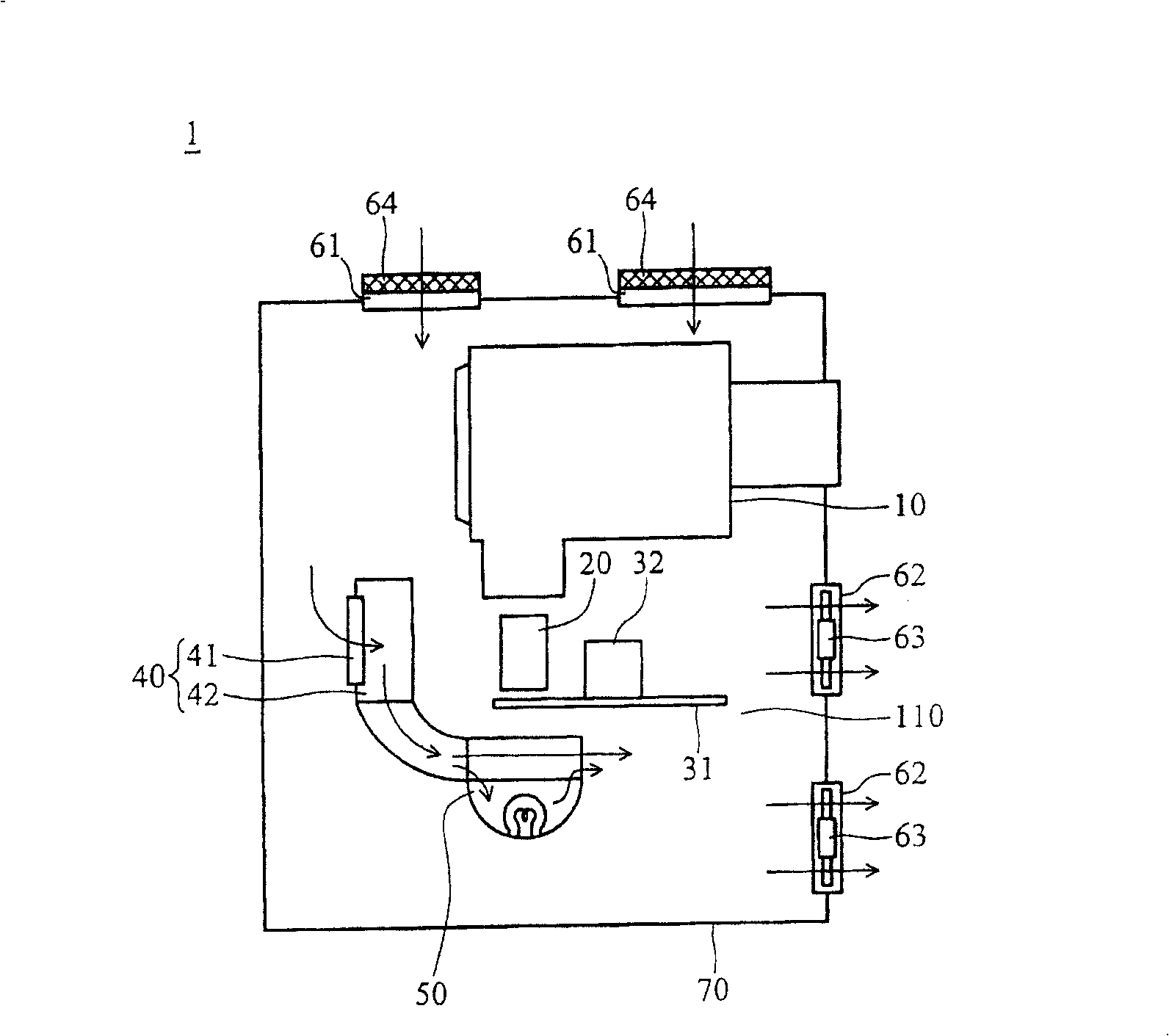
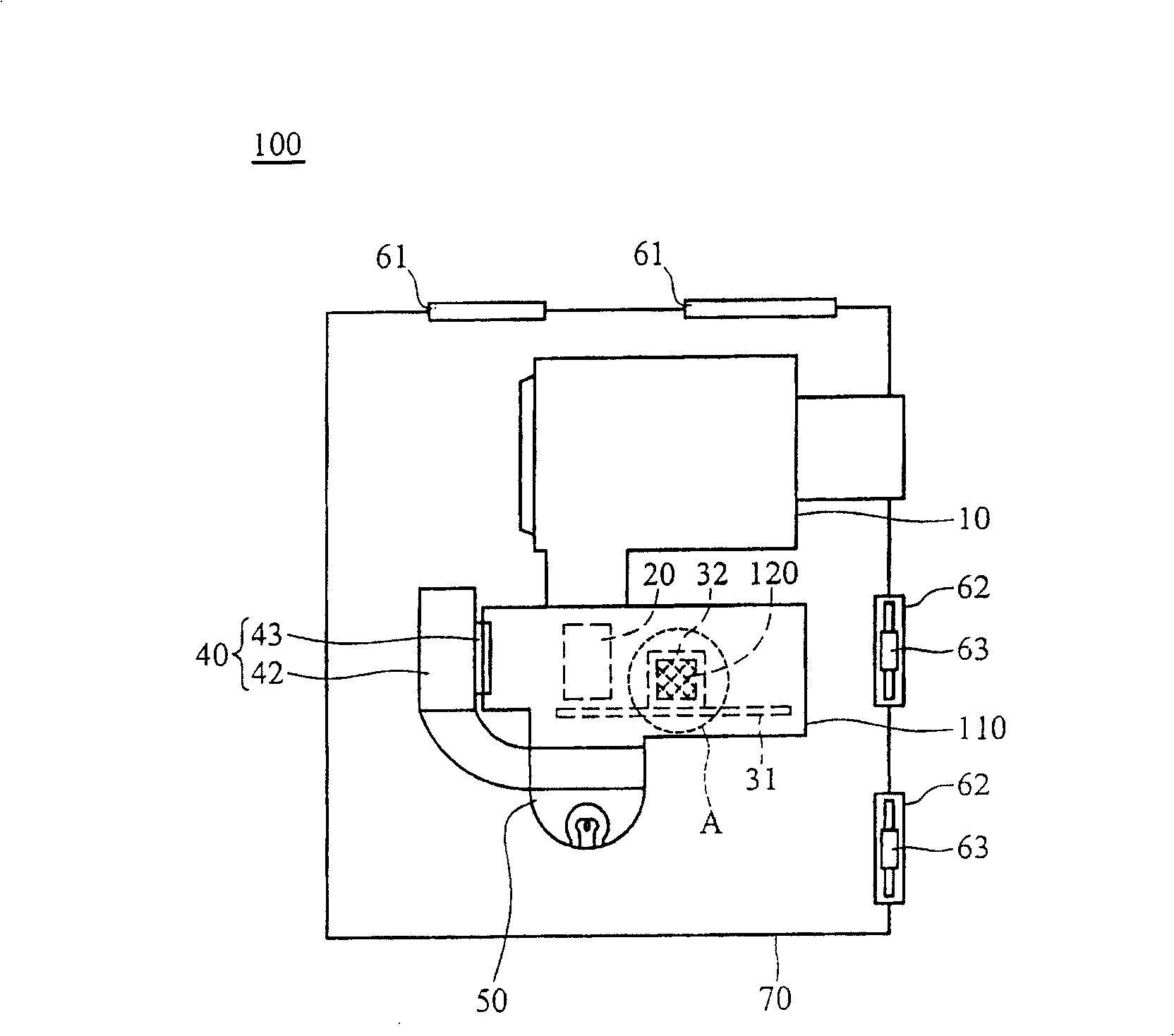
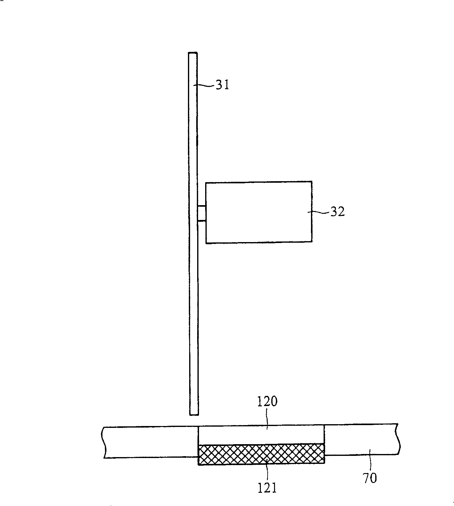
[0038] refer to Figure 2a , which shows the projector 100 according to the first embodiment of the present invention, including a lens module 10, a light guide pipe 20, a color wheel 31, a color wheel motor 32, a fan module 40, a light source module 50, and a system air inlet 61 , the system air outlet 62 , a casing 70 , a wind guide cover 110 and a first air inlet 120 . The lens module 10 , the light pipe 20 , the color wheel 31 , the color wheel motor 32 , the fan module 40 , the light source module 50 and the air guide cover 110 are disposed in the casing 70 . The system air inlet 61 , the system air outlet 62 and the first air inlet 120 are opened on the housing 70 . The first air inlet 120 is located below the color wheel motor 32, and corresponds to the color wheel motor 32. Figure 2b , which shows Figure 2a In the side view of part A, the first air inlet 120 is provided with a filter screen 121 . A system fan 63 is disposed in the system air outlet 62 . The fan ...


PUM


Abstract

The invention discloses a projector, comprising a wind scooper, a color wheel, a motor of color wheel, a light pipe and a first air inlet. The color wheel is set in the wind scooper. The motor of color wheel is connected with the color wheel and in the wind scooper. The light pipe is in the wind scooper and corresponds with the color wheel. The first air flow enters into the wind scooper from the first air inlet and passes through the motor of the color wheel and light pipe and flows out the wind scooper.

Description

technical field [0001] The invention relates to a projector, in particular to a projector capable of improving heat dissipation efficiency. Background technique [0002] refer to figure 1 Figure, which shows the existing projector 1, including a lens module 10, a light pipe 20, a color wheel 31, a color wheel motor 32, a fan module 40, a light source module 50, a system air inlet 61, a system outlet Air port 62 and housing 70 . The lens module 10 , the light pipe 20 , the color wheel 31 , the color wheel motor 32 , the fan module 40 and the light source module 50 are disposed in the casing 70 . The system air inlet 61 and the system air outlet 62 are disposed on the casing 70 . The system air inlet 61 is provided with a filter screen 64 to isolate dust from the outside. The system air outlet 62 is provided with a system fan 63 to drive air flow. The fan module 40 includes an air inlet 41 and a heat dissipation fan 42 . The heat dissipation fan 42 drives an airflow into ...

Claims


Application Information

Patent Timeline
IPC IPC(8): G03B21/16G03B21/00H05K7/20
Inventor 李长坚吕圣章
Owner BENQ CORP
Why Eureka
Try Eureka