
Insert shaft type hub electric motor and electric automobile

A technology for in-wheel motors and electric vehicles, applied in the field of electric vehicles, can solve the problems of inconvenience in mass production and daily maintenance, reduced reliability of electrical connections, inconvenient loading and unloading of driving wheels, etc. Easy to use and dismantle

Active Publication Date: 2008-09-03
董建国
View PDF0 Cites 20 Cited by
  • Summary
  • Abstract
  • Description
  • Claims
  • Application Information

AI Technical Summary

Problems solved by technology

For electric vehicles using in-wheel motors, since the stator of the in-wheel motor is directly fixed on the wheel shaft of the car, the wheel hub rotor located on the periphery of the stator and also used as the motor casing is also installed on the wheel shaft through the bearings on both sides, making the wheel shaft of the car a The hub motor is an essential installation base frame. After the hub motor with this structure is assembled, the hub motor cannot be dismantled from the hub shaft as a whole, because once removed, the stator and rotor of the hub motor will lose their installation. The base frame is misplaced and falls apart, not integrated
The use of such hub motors in electric vehicles makes it very inconvenient to load and disassemble the driving wheels, which is not convenient for mass production and daily maintenance; in addition, all the wires of this hub motor are passed through the threading holes inside the car wheel shaft or other places. In vitro, connecting with the exposed controller wire connector not only adds a manual connection process, but also reduces the reliability of the electrical connection

Method used


Image

  • Insert shaft type hub electric motor and electric automobile
  • Insert shaft type hub electric motor and electric automobile
  • Insert shaft type hub electric motor and electric automobile

Examples


Embodiment Construction

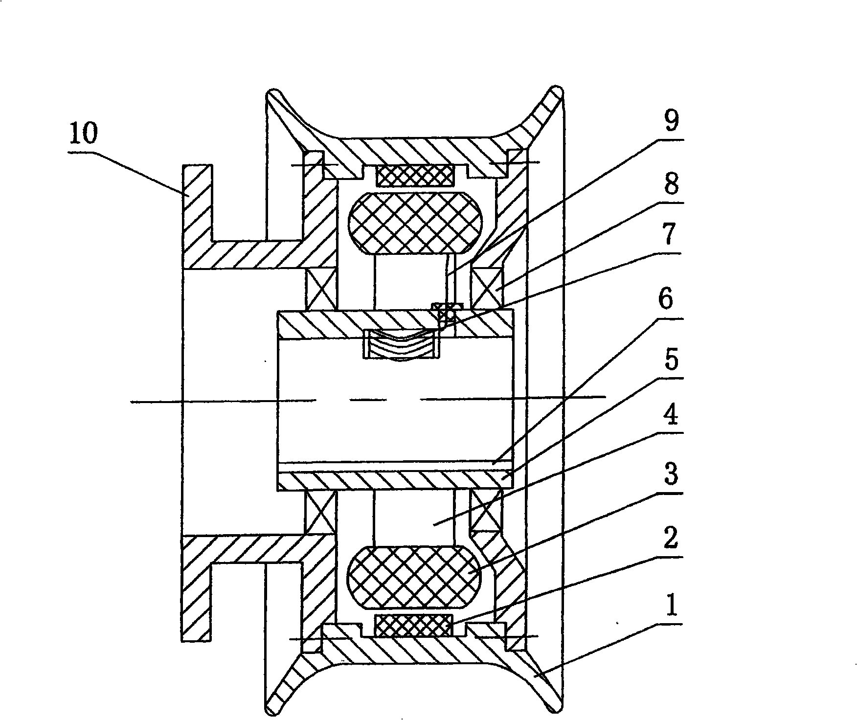
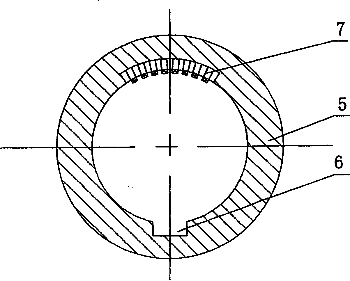
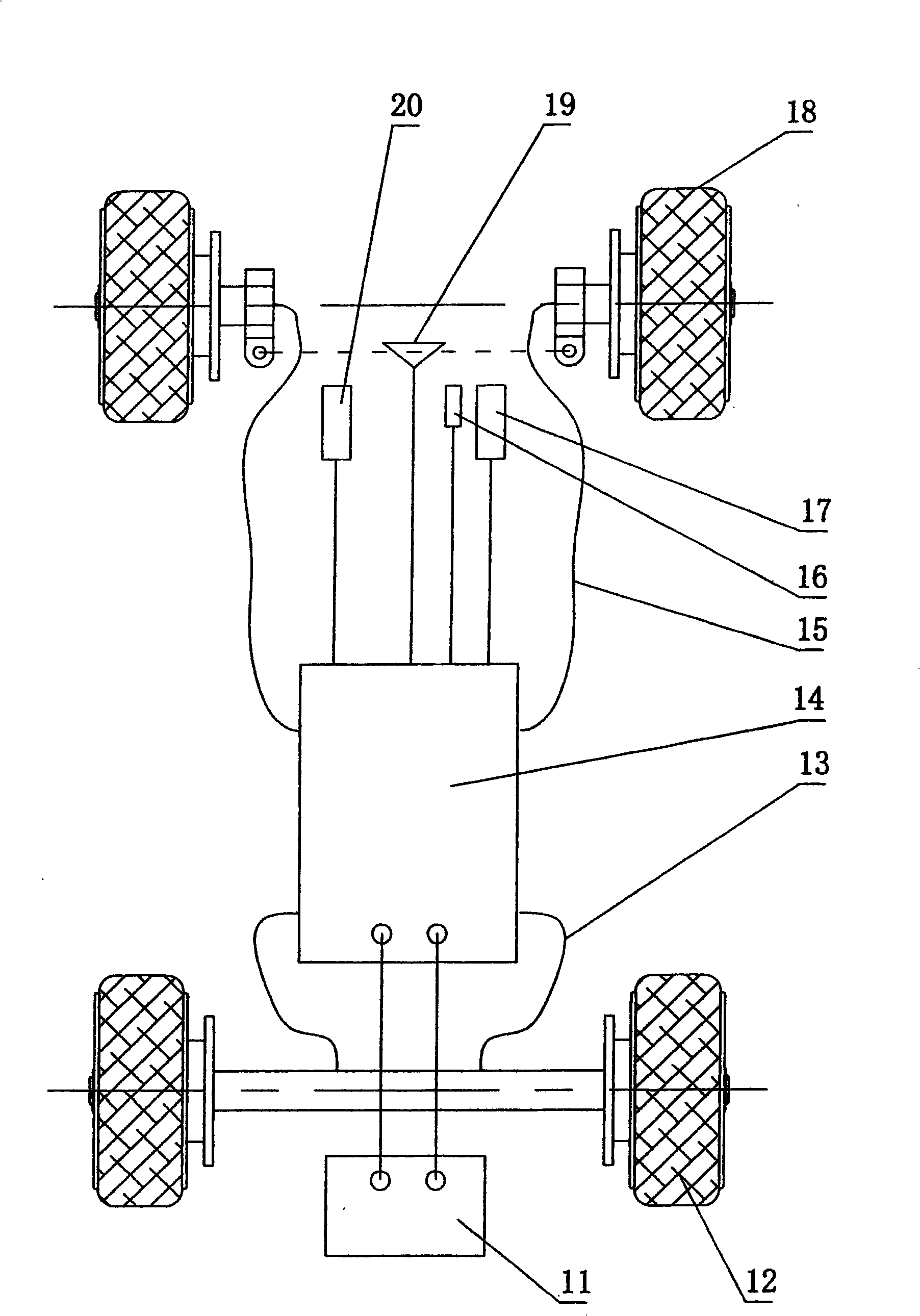
[0026] figure 1 , figure 2 The shaft-inserted hub motor shown includes a shaft sleeve 5, and a stator is fixed on the outer wall of the shaft sleeve. The stator includes a coil 3 and a stator bracket 4 installed on the shaft sleeve. Bearing 8 is arranged, and the hub rotor 1 that is positioned at the periphery of the stator and also serves as the motor casing is installed on the bearing 8, and there is a magnetic steel 2 on the inner wall of the hub rotor. The inner wall of the shaft sleeve is provided with an axially penetrating keyway 6, the middle section of the inner wall of the shaft sleeve is provided with a sinking groove at the position opposite to the keyway, and one end of the sinking groove is provided with a hole that communicates with the sinking groove and penetrates radially through the sleeve wall. The wire passes through the hole, and the sinker is embedded with an elastic electrical connection terminal 7. The motor coil lead wire 9 passes through the wire t...


PUM


Abstract

The invention relates to an inserting shaft type hub motor and an electric automobile using the motor. The inserting shaft type hub motor includes an axle sleeve, a stator is fixedly installed on the ektexine of the axle sleeve, bearings are respectively provided on both sides of the ektexine of the axle sleeve, a hub rotor is installed on the bearings, and a driving wheel is inserted and installed at the corresponding position of the axletree through the bearings. The inner wall of the axle sleeve is provided with key grooves run-through axial direction and first elastic electrically connecting terminals electrically connected with the motor coils, the axletree is correspondingly provided with keys matched with the key grooves and second elastic electrically connecting terminals electrically connected with the automobile controller, the first and second electrically connecting terminals are automatically electrically connected after the driving wheel is installed at the axletree, thereby the circuit connecting the motor rotor coil and the automobile controller allows the circuit connection to be simple and credibility, and allows the assemble and unassemble, use and maintaining of the hub motor and driving wheel on the electric automobile.

Description

technical field [0001] The invention relates to the technical field of electric vehicles, in particular to a hub motor and an electric vehicle using the hub motor. Background technique [0002] The hub motor is a mature mechanical and electrical product, which has been widely used in electric bicycles, and its application in the field of electric vehicles has also begun. For electric vehicles using in-wheel motors, since the stator of the in-wheel motor is directly fixed on the wheel shaft of the car, the wheel hub rotor located on the periphery of the stator and also used as the motor casing is also installed on the wheel shaft through the bearings on both sides, making the wheel shaft of the car a The hub motor is an essential installation base frame. After the hub motor with this structure is assembled, the hub motor cannot be dismantled from the hub shaft as a whole, because once removed, the stator and rotor of the hub motor will lose their installation. The pedestals ...

Claims


Application Information

Patent Timeline
Patent Type & Authority Applications(China)
IPC IPC(8): H02K7/14B60K7/00B60K1/02
CPCY02T10/641Y02T10/64
Inventor 董建国
Owner 董建国
Learn More