
Imaging apparatus, driving method thereof, and imaging system

A technology of imaging equipment and driving method, which is applied in the parts of TV system, scanning details of TV system, image communication, etc., can solve the problems of pixel leakage and achieve the effect of reducing leakage

Active Publication Date: 2008-09-03
CANON KK
View PDF2 Cites 0 Cited by
  • Summary
  • Abstract
  • Description
  • Claims
  • Application Information

AI Technical Summary

Problems solved by technology

This in turn causes photoelectric charges to leak from pixels in the non-readout region into pixels in the readout region

Method used


Image

  • Imaging apparatus, driving method thereof, and imaging system
  • Imaging apparatus, driving method thereof, and imaging system
  • Imaging apparatus, driving method thereof, and imaging system

Examples


Embodiment Construction

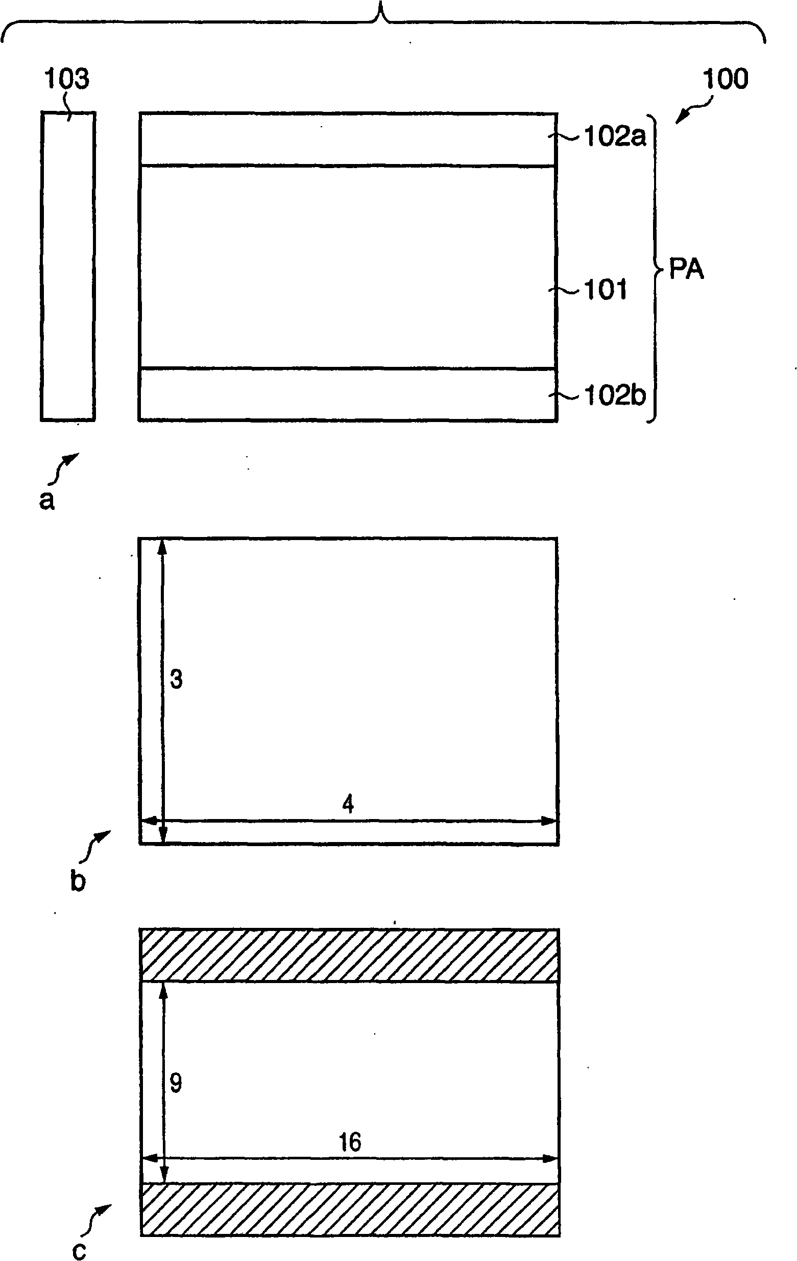
[0026] will refer to figure 1 The imaging apparatus 100 according to the first embodiment of the present invention will be described. figure 1 is a diagram of an imaging apparatus 100 according to a first embodiment of the present invention.

[0027] Such as figure 1 As shown, the imaging device 100 has a pixel array PA and a driving unit 103 .

[0028] In the first mode, the pixel array PA has a readout area 101 and non-readout areas 102a and 102b. Signals are read out from the pixels in the readout area 101 in the first mode. Signals are not read out from pixels in the non-readout areas 102a and 102b in the first mode. Therefore, the image obtained in the first mode has figure 1 The 16:9 aspect ratio shown in c. The readout area 101 includes selected pixels, which are pixels in a row selected to be readout, and unselected pixels, which are pixels in other rows.

[0029] In the second mode, signals are read out from all pixels in the pixel array PA. Therefore, the ima...


PUM


Abstract

The present invention provides an image apparatus and its driving method, and image system. In an imaging apparatus according to the present invention, the driving unit drives each of the pixels in the non-readout region in the first mode such that the setting unit sets the input unit to a third electric potential with the transfer unit being ready to transfer the electric charge to reset the photoelectric conversion unit in a first period and that the setting unit sets the input unit to a fourth electric potential for the pixel to be deselected in a second period later than the first period.

Description

technical field [0001] The present invention relates to an imaging device, a driving method thereof, and an imaging system. Background technique [0002] Recently, with the spread of HDTV (High Definition Television), there has been a demand for an imaging device that takes moving images with an aspect ratio of 16:9. On the other hand, it is desirable to capture still images with an aspect ratio of 4:3 because photographic paper has an aspect ratio of about 4:3. Thus, in order to realize an imaging device that supports both moving images and still images, it is necessary to be able to switch the aspect ratio between the 16:9 mode and the 4:3 mode. This imaging device has an overall imaging area of ​​4:3 aspect ratio and reads out all pixel signals in 4:3 mode. In 16:9 mode, the imaging device only reads out the signal of the pixel in the center (the readout area where the signal is read out from the pixel), and does not read out the top and bottom (the non-readout area whe...

Claims


Application Information

Patent Timeline
Patent Type & Authority Applications(China)
IPC IPC(8): H04N3/15H01L27/146H04N25/00H04N25/42
Inventor 小野俊明野田智之高桥秀和
Owner CANON KK
Learn More