Time-temperature indicators

A technology of indicators and objects, applied in the field of temperature indicators

Inactive Publication Date: 2008-09-03
AUSTRALIEN NAT UNIV
View PDF5 Cites 17 Cited by
  • Summary
  • Abstract
  • Description
  • Claims
  • Application Information

AI Technical Summary

Problems solved by technology

A limitation of the indicator of the invention described in this reference is that only one critical temperature can be monitored

Method used


Image

  • Time-temperature indicators
  • Time-temperature indicators
  • Time-temperature indicators

Examples


Embodiment 1

[0065] Example 1. Wax composition

[0066] Prepared by combining paraffin wax (product number BA693) from Walker Ceramics, Victoria Australia; liquid paraffin (product number 76233) CAS [8002-72-2] from Fluka and a commercially available candle wax dye and test wax compositions.

[0067] The melting point of solid paraffin was determined to be 58-62°C.

[0068] The mixture of wax and dye is combined and mixed together at a temperature above the melting point of the highest component and solidifies before the approximate melting point is determined. The dye contains 0.5-1.0 wt% of the mixture. Approximate melting points were determined visually using an oven and the results are listed in Table 1 below.

[0069] Table 1. Wax compositions and approximate melting points

[0070] Solid wax Wt%

Liquid wax Wt%

Melting point °C

note

15

85

31

colorless

20

80

39

colorless

25

75

40

blue ...

Embodiment 2

[0073] Example 2. Dye Compositions

[0074] Various candle dyes are used to color paraffin wax. The colors used are red, yellow and blue. Wax compositions containing 0.5-1.0 wt% candle dye were observed to have a melting point of -1-3°C higher than wax compositions without the dye. It is believed that this simply reflects the higher melting point of the wax base of the dye material.

[0075] A mixture of dyes was added to the wax composition and it was observed that the mixture of colored dyes could be used to provide a variety of different colors. Red and yellow dyes provide orange wax compositions. Similarly, blue and red dyes produce purple wax compositions, and blue and yellow produce green wax compositions.

Embodiment 3

[0076] Example 3. Visible Thermal History Indicators

[0077] A series of experiments were performed to investigate the properties of the waxes when heated above their melting temperature.

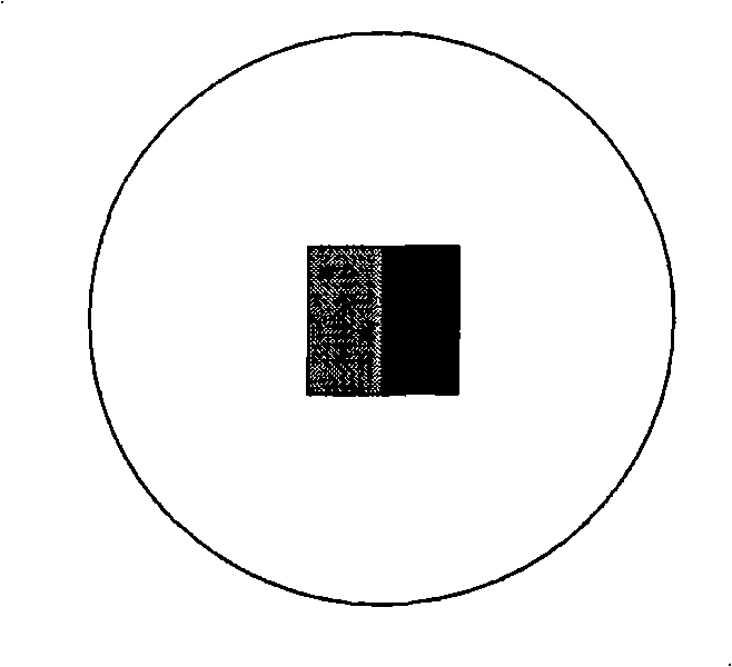
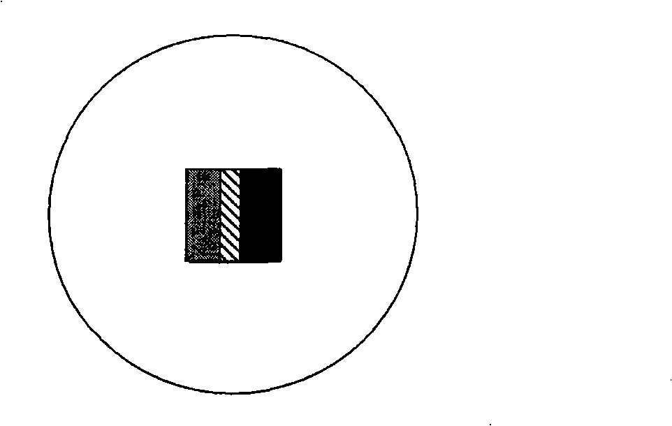
[0078] refer to figure 1 , in a 60mm diameter glass Petrie dish, place a strip of yellow wax (indicated by hashes) and blue wax (indicated by solid black) to a depth of approximately 1mm. The sides of the two wax strips touch each other. Molten colorless wax having a melting point higher than the two colored waxes was added to the dish and surrounded the colored wax strips and allowed to cool and solidify prior to testing.

[0079] Heat the plate and wax in an oven at a temperature above the melting point of the colored wax but below the melting point of the colorless wax for one hour, then cool.

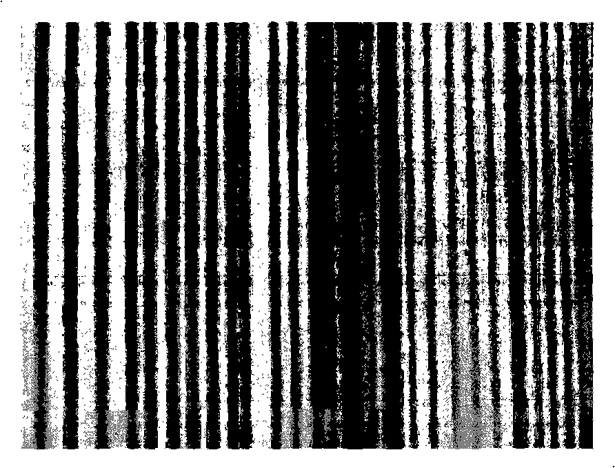
[0080] exist figure 2 The heating result is displayed in . It was found that the initial color wax mixed in the area close to the contact area of ​​the two bars. The central region (rep...


PUM

PropertyMeasurementUnit
softening pointaaaaaaaaaa
freezing pointaaaaaaaaaa
melting pointaaaaaaaaaa

Abstract

The present invention provides a visual thermal history indicator comprising a pattern produced from at least two waxes wherein one wax has a melting point that differs from the other wax, or where the waxes have the same melting point but different melt flow behaviour, and wherein the pattern is adapted so that when the lower melting point wax melts or the wax with greater melt flow behaviour flows, the visual appearance of the pattern changes, and wherein when the second and subsequent higher melting waxes melt, or when the lower melt flow behaviour waxes flow, the visual appearance of the pattern changes as each wax melts or flows.

Description

technical field [0001] The present invention relates to a temperature indicator which can be applied directly or indirectly by deposition on the packaging of perishable or heat-sensitive products. The temperature indicators are formed from wax-based inks and can additionally be applied directly or indirectly to the product by deposition to provide information about the thermal history of the product. Background technique [0002] It is desirable to provide an indication of whether a product has been exposed to an undesirable time-temperature history. This applies to perishable items such as food and medicine. These products generally have a limited useful life, which may be significantly shortened by exposure to relatively high temperatures for a specified period of time during storage, distribution or use. [0003] It may also find application when a predetermined time-temperature history is required during processing or use of the product. It also concerns certain produ...

Claims


Application Information

Patent Timeline
Patent Type & Authority Applications(China)
IPC IPC(8): G01K11/06G01K1/06G01K3/10G01N31/22
CPCG01K1/02G01K3/04G01K11/06G01N31/229
Inventor 文森特·克雷格蒂莫西·J·森登克里斯琴·库吉
Owner AUSTRALIEN NAT UNIV
Why Eureka
Try Eureka