

Eyeball component
A technology of eyeballs and components, applied in entertainment, toys, dolls, etc., can solve problems such as slow response speed, rigid changes, slow response speed of machine eyeballs, etc.
- Summary
- Abstract
- Description
- Claims
- Application Information
AI Technical Summary
Problems solved by technology
Method used
Image

Examples
no. 1 example
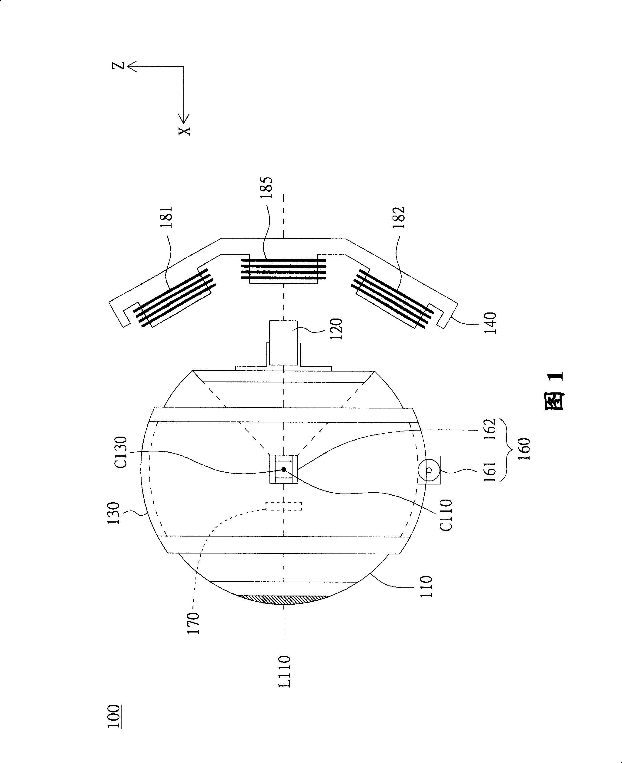
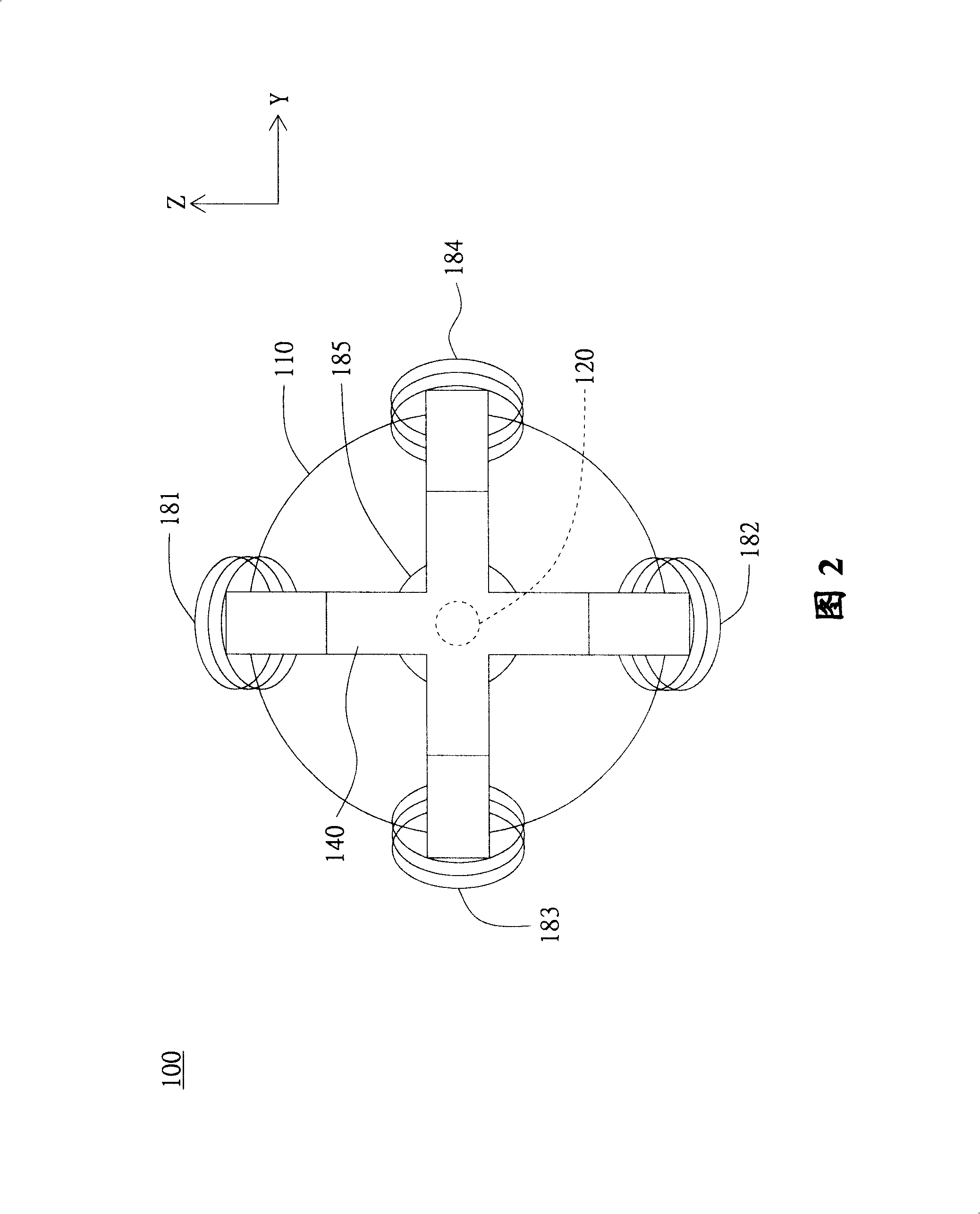
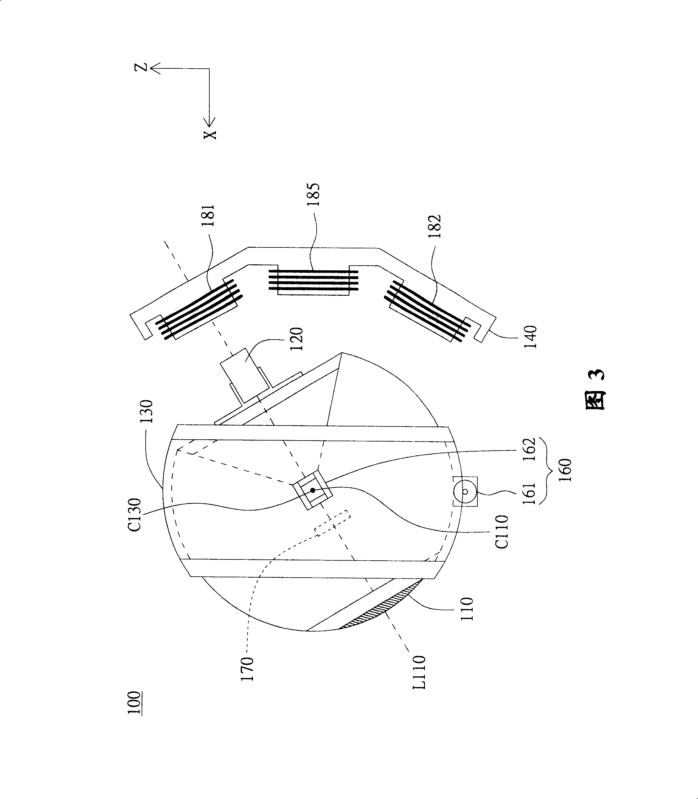
[0050] Please refer to FIG. 1 , which shows a schematic diagram of an eyeball assembly 100 according to a first embodiment of the present invention. The eyeball assembly 100 at least includes an eyeball body 110, a magnetic element 120, a housing 130, and a plurality of electromagnetic coils (only the electromagnetic coil 181, the electromagnetic coil 182, and the electromagnetic coil 185 are shown in FIG. 1). The shape of the eyeball body 110 is a sphere. The magnetic element 120 is arranged on the eyeball body 110 . The housing 130 is used for accommodating part of the eyeball body 110 so that the eyeball body 110 can rotate in the housing 130 . A plurality of electromagnetic coils are arranged behind the eyeball body 110 . Wherein, at least one electromagnetic coil acts relative to the magnetic element 120 to drive the eyeball body 110 to rotate.
[0051] Each electromagnetic coil is wound with surface insulated wires in one direction, and generates magnetic force by ene...
no. 2 example
[0070] The difference between the eyeball assembly 200 of this embodiment and the eyeball assembly 100 of the first embodiment lies in the number of electromagnetic coils and their arrangement positions, and the rest of the similarities will not be repeated here. Please refer to FIG. 9 , which shows a schematic diagram of the electromagnetic coil and the fixing member of the eyeball assembly 200 according to the second embodiment of the present invention. In this embodiment, the eyeball assembly 200 includes three electromagnetic coils 281 , 282 , 283 respectively arranged at three ends of the fixing seat 240 . Preferably, the three endpoints are arranged in an equilateral triangle.
[0071] When the three electromagnetic coils 281, 282, 283 all produce equal amounts of active force relative to the magnetic element 120, the combined active force of the three active forces is facing the central axis of the eyeball body 110 (the central axis is not shown in Figure 9 ), so that ...
no. 3 example
[0075] The difference between the eyeball assembly 300 of this embodiment and the eyeball assembly 100 of the first embodiment lies in the number of electromagnetic coils 381 and their arrangement positions, and the rest of the similarities will not be repeated here. Please refer to FIG. 10 , which shows a schematic diagram of an electromagnetic coil 381 and a fixing member 340 according to a third embodiment of the present invention. In this embodiment, a plurality of electromagnetic coils 381 are disposed on the fixing seat 340 around the magnetic element 120 (the magnetic element 120 is indicated by a dotted line). Preferably, the electromagnetic coils 381 are symmetrically arranged around the magnetic element 120 . Likewise, these electromagnetic coils 381 can simultaneously, partially or individually generate force against the magnetic element 120 . The eyeball assembly 300 can design the quantity and arrangement position of the electromagnetic coils 381 according to pro...
PUM
 Abstract
Description
Claims
Application Information