Ball hinge device based on flexible member

A flexible element and ball hinge technology, applied in the field of positioning support and connecting mechanism, can solve the problems of difficult realization of rotational freedom, affecting the rigidity, range of motion and life of flexible hinges, large torsional rigidity, etc. Processing and installation process requires loose effect

Inactive Publication Date: 2010-06-02
NANJING INST OF ASTRONOMICAL OPTICS & TECH NAT ASTRONOMICAL OBSE
View PDF7 Cites 2 Cited by
  • Summary
  • Abstract
  • Description
  • Claims
  • Application Information

AI Technical Summary

Problems solved by technology

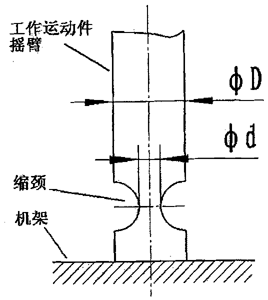
[0003] Flexible elements, such as flexible hinges, are often used to overcome the above-mentioned shortcomings of ball joints based on bearing mechanisms, see figure 1 The rocker arm of the working moving part adopts a necking method near the end to form a part with less rigidity, thereby allowing the rocker arm of the moving part to rotate within a small range of angles, but the third rotation along its axis is free The degree of rigidity is not easy to achieve, because the torsional stiffness of the constriction part is relatively large; moreover, the design of the constriction directly affects the stiffness, range of motion and life of the flexible hinge

Method used


Image

  • Ball hinge device based on flexible member
  • Ball hinge device based on flexible member
  • Ball hinge device based on flexible member

Examples


Embodiment 1

[0045] Embodiment 1, the ball hinge mechanism based on flexible elements see Image 6 , Figure 7 , Figure 8 , three through holes slightly larger than the steel wire 4 are drilled orthogonally on the ball joint 6, and the center is drilled with a hollow as large as possible so that the three steel wires 4 (the third vertical paper surface) can pass through, and the moving parts are connected by threads rocker arm 1. In order to eliminate the gap and maintain stability, after the three steel wires 4 pass through the corresponding small holes on the ball joint 6, the steel wires 4 and the corresponding holes on the ball joint 6 are filled tightly by brazing. Then, move the rocker arm 1 through the middle hole of the upper pressing plate 2 . The size of the hollow of the upper pressing plate 2 is designed according to the angle range that the ball joint needs to work, so as to prevent the moving part rocker arm 2 from exceeding the working angle orientation, thereby causing ...


PUM


Abstract

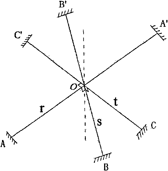
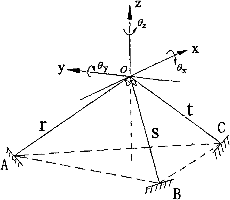
The invention discloses a flexible component-based spherical hinge mechanism provided with an operationally moving (a rockerarm). The mechanism is characterized in that three identical slender steel wires are provided, which are orthogonally positioned at the middle point O, two ends of the three steel wires are respectively fixed, and the ball joint point of the operationally moving part is connected with the three steel wires at the O point. 'the ball joint point of the operationally moving part is connected with the three steel wires at the O point' in the optimal proposal adopts the following connecting mode that: three through holes little larger than the steel wires are orthogonally drilled on the ball joint point, the center is drilled into hollowness as large as possible, so that the three steel wires are capable of going through the center, and the operationally moving part (the rockerarm) is connected through threads. The invention allows three rotational freedoms within small angle range for the connected operationally moving part, but three translational freedoms are limited; the spherical hinge mechanism is capable of realizing sphere higher pair functions of no clearance, no friction, constant rigidity in any translational direction, and constant flexibility in any rotation direction.

Description

technical field [0001] The invention relates to a ball joint mechanism based on a flexible element, which is a positioning support and connection mechanism especially suitable for objects that rotate precisely at a small angle and whose working posture needs to be changed. Background technique [0002] As a spherical joint, the spherical joint constrains three degrees of freedom in translation and leaves three degrees of freedom in rotation. Traditionally, ball joints are generally realized by mechanisms such as joint bearings or spherical ball bearings. This method can make the motion mechanism have greater load capacity and rigidity. However, in addition to the complicated installation and maintenance of the bearing mechanism, friction and clearance are more difficult. problem to overcome. In particular, when the connected objects need to do precise motion (for example, the spherical high pair on the astronomical telescope), friction and clearance are extremely harmful; a...

Claims


Application Information

Patent Timeline
Patent Type & Authority Patents(China)
IPC IPC(8): F16C11/06
Inventor 杨德华陈昆新
Owner NANJING INST OF ASTRONOMICAL OPTICS & TECH NAT ASTRONOMICAL OBSE
Why Eureka
Try Eureka