
Inner fork chute type axially sliding constant-velocity-ratio universal joint

An inner fork slideway type, constant velocity universal joint technology, applied in the direction of couplings, elastic couplings, mechanical equipment, etc., can solve the problem of affecting product assembly clearance, performance and efficiency, poor anti-centrifugal and anti-deformation effects, Increase raw material consumables and other issues to achieve good assembly effect, low cost, and simplified structure

Active Publication Date: 2010-06-09
GSP AUTOMOTIVE GRP WENZHOU
View PDF4 Cites 0 Cited by
  • Summary
  • Abstract
  • Description
  • Claims
  • Application Information

AI Technical Summary

Problems solved by technology

The current sliding end universal joint usually adopts the tripod type axial sliding constant velocity universal joint. This kind of universal joint has the following disadvantages: 1. The ball track is integrally arranged in the inner cavity of the shell so that the wall thickness of the inner cavity Need to increase a lot, which greatly increases the consumption of raw materials
3. It is easy to deform the fairway after intermediate frequency heat treatment. Since the fairway of the shell is in a semi-closed state, it is impossible to reprocess the fairway after heat treatment, so the matching gap between the ball ring rolling on the fairway and the fairway is not consistent, which will affect the The assembly clearance and performance and efficiency of the product ultimately affect the quality of the product
5. The appearance of the dust cover is a deep corrugated rotary rubber part, and the length is long, the shape is complex, the manufacturing cost is high, the effect of anti-centrifugation and anti-deformation is poor, and it is easy to be damaged

Method used


Image

  • Inner fork chute type axially sliding constant-velocity-ratio universal joint
  • Inner fork chute type axially sliding constant-velocity-ratio universal joint
  • Inner fork chute type axially sliding constant-velocity-ratio universal joint

Examples


Embodiment Construction

[0011] Embodiments of the present invention are now described in detail in conjunction with the accompanying drawings:

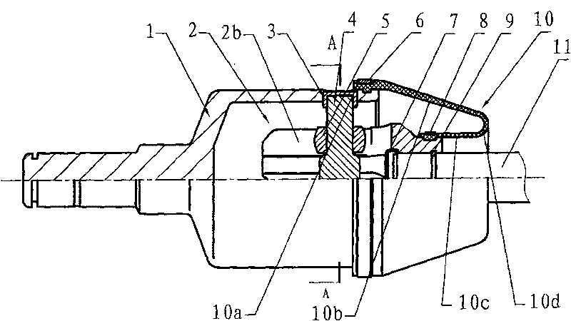
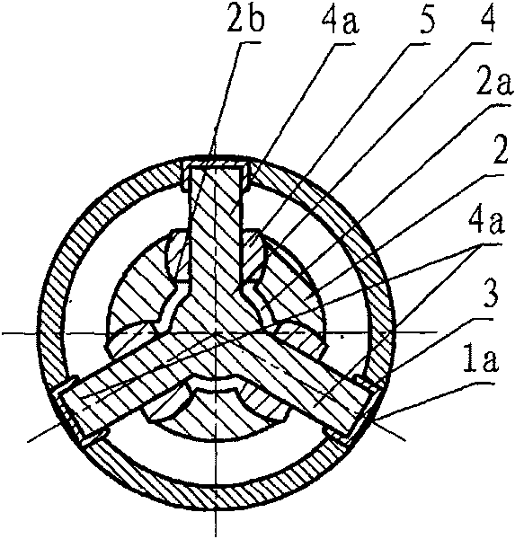
[0012] Such as figure 1 , figure 2 As shown, an embodiment of an inner fork slideway type constant velocity universal joint that can slide axially in the present invention includes a housing 1 and a three-pin frame 4 , each leg of which is slidably sleeved on the three-pin frame 4 The ball ring 5 on the shaft 4a, the ball lane and the dust cover 10 matched with the ball ring 5 also include a three-pointed joint 2, and the three-pointed joint 2 is uniformly distributed in the circumferential direction with three ballways 2b (uniformly distributed in the circumferential direction refers to three ballways). 2b is distributed in three equal parts on the circumference of the trident), the axis is provided with a member with a central hole 2a, the trident 2 is fixed on one end of the intermediate shaft 11, and the central hole 2a communicates with the three ball...


PUM


Abstract

The invention relates to an automobile transmission gimbal joint, in particular to an inner fork slideway type axially slidable constant speed gimbal joint, comprising a housing, a three-pin shelf, ball rings respectively and slidably sleeved on each foot axis of the three-pin shelf, ball paths matched with the ball rings, and a dirt shroud. The gimbal joint is characterized in that the gimbal joint further comprises a trifurcate joint which is a component on which three ball paths are circumferentially arranged, and the axle center of which is provided with a center hole. The trifurcate jointis fixed on one end of a middle shaft, and the center hole is radially communicated with the three ball paths. The center hole and the three ball paths are axially communicated with the end surface of the end of the middle shaft and the end on which the trifurcate joint is fixed. The three-pin shelf is sleeved on the trifurcate joint. The ball rings sleeved on the foot axis of the three-pin shelfand the ball paths form rolling or / and sliding fit. The three-pin shelf is fixed on the inner cavity of the housing. The gimbal joint is low in production cost, high in assembly precision and stablein product quality.

Description

technical field [0001] The invention relates to an automobile transmission universal joint, in particular to an inner fork slideway type constant velocity universal joint capable of sliding axially. Background technique [0002] The transmission shaft used for automobile power transmission is generally composed of a fixed end universal joint, an intermediate shaft and a sliding end universal joint. The fixed end universal joint is connected to the wheel end of the vehicle, and the sliding end universal joint is connected to the engine end. The current sliding end universal joint usually adopts the tripod type axial sliding constant velocity universal joint. This kind of universal joint has the following disadvantages: 1. The ball track is integrally arranged in the inner cavity of the shell so that the wall thickness of the inner cavity It needs to be enlarged a lot, which greatly increases the consumption of raw materials. 2. The shell blank with three ballways needs to b...

Claims


Application Information

Patent Timeline
Patent Type & Authority Patents(China)
IPC IPC(8): F16D3/205
CPCF16D3/207
Inventor 周俭
Owner GSP AUTOMOTIVE GRP WENZHOU
Learn More