Reverse converter

A converter and reverse technology, applied in the direction of belt/chain/gear, mechanical equipment, transmission device, etc., can solve the problems of large outline size, complex structure, heavy weight, etc., and achieve compact structure, large stirring power, low weight Reduced effect

Inactive Publication Date: 2008-09-10
SHANGHAI NORMAL UNIVERSITY
View PDF0 Cites 3 Cited by
  • Summary
  • Abstract
  • Description
  • Claims
  • Application Information

AI Technical Summary

Problems solved by technology

These two methods all have the problems of complex structure, large outline size, large volume, heavy weight and high cost

Method used


Image

  • Reverse converter
  • Reverse converter
  • Reverse converter

Examples


Embodiment

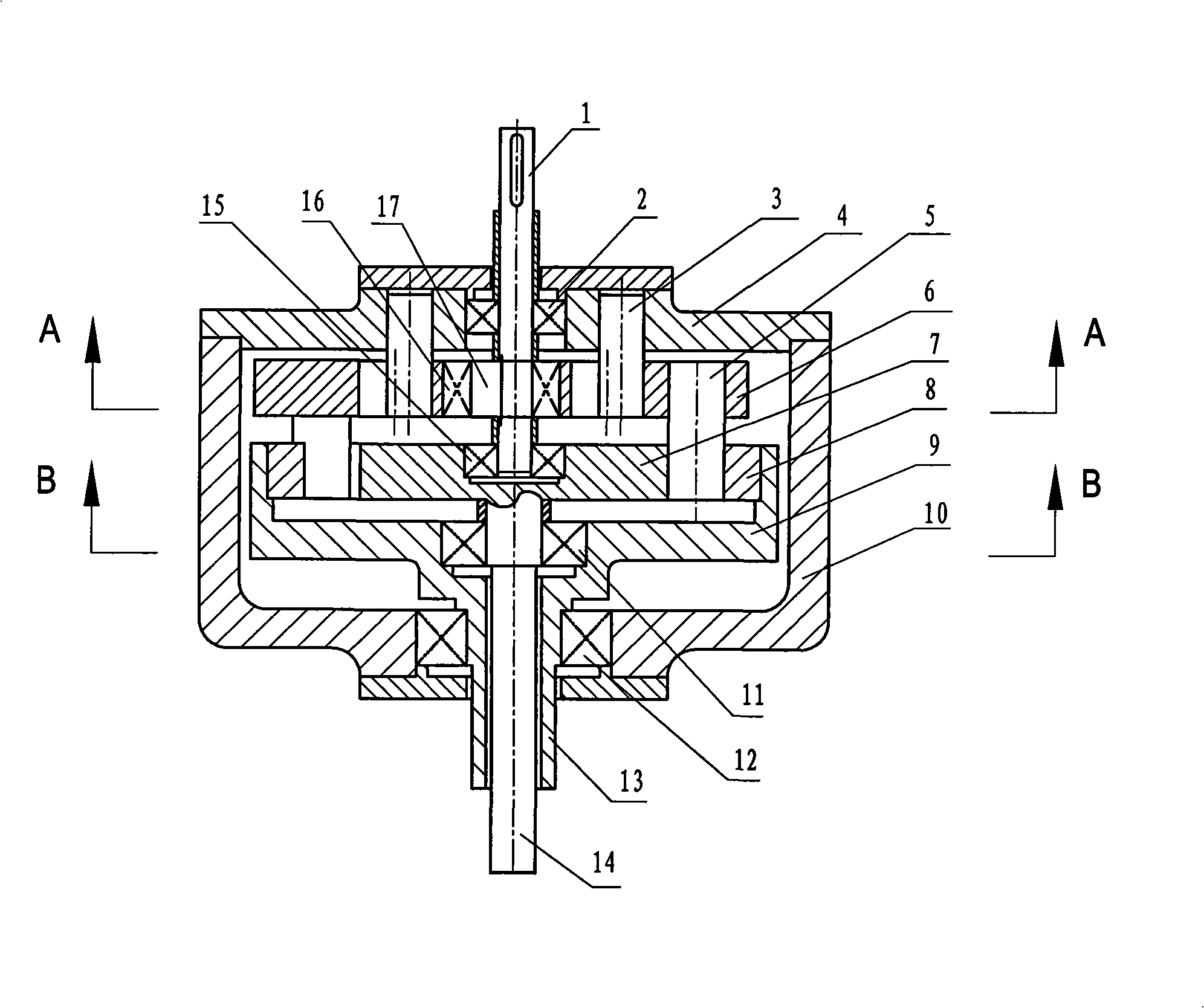
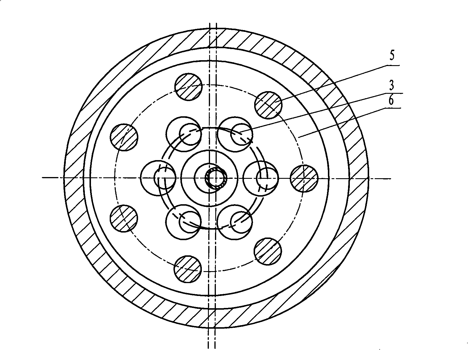
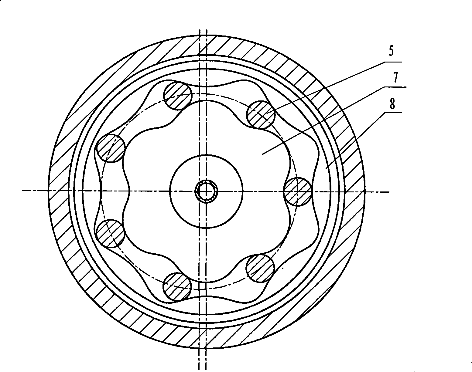
[0037] see figure 1 , 2 , 3. This example is mainly composed of input shaft 1, front bearing 2, output disc bearing 11, sleeve bearing 12, inner rotor bearing 15, eccentric bearing 16, column pin 3, front cover 4, pin teeth 5, and translation disc 6 , Inner rotor 7, outer rotor 8, output disk 9, box 10, output sleeve 13, output shaft 14 and eccentric shaft 17 and other components. The input shaft 1 is fixedly connected with the eccentric shaft 17 as a whole, and is not coaxial with the output shaft 14, but coincides with the axes of the output shaft 14 and the output sleeve 13. The inner rotor 7 and the output shaft 14 are fixedly connected as one. The inner rotor 7 of the epicycloid wheel has 6 teeth less than the pin tooth 5, and the inner cycloid ring gear of the outer rotor 8 has 8 teeth more than the pin tooth 5. The outer rotor 8 is fixedly connected with the output disk 9 and the output sleeve 13 as a whole, and the inner rotor 7 and the outer rotor 8 respectively mes...


PUM


Abstract

The invention discloses a structure for a mechanical direction changing device. In a reverse converter, an input shaft (1) is fixedly connected and integrated with a centrifugal shaft (17), and is disconnected with an output shaft (14), and is in superposition with the axis of the output shaft (14) and an output sleeve barrel (13); an internal rotor (7) of a short amplitude epicycloidal gear is fixedly connected and integrated with the output shaft (14). The external rotor (8) of a short amplitude hypocycloid ring gear is fixedly connected and integrated with an output plate (9) and the output sleeve barrel (9). The internal rotor (7) and the external rotor (8) are respectively meshed with pin gears (5)inbetween; A dowel pin (3) is fixed on a front cover (4). The pin gears (5) are fixed on a translatory plate (6) which is provided with a plurality of dowel pin holes. The pin gears (5) are circumferentially and uniformly fixed on the translatory plate (6) which is arranged on a part of the centrifugal shaft (17) of the output shaft (1) through a bearing (16). The invention is compact in structure, reduced in volume and reduced in weight, compared with the rotate speed of the input shaft (1), compared with the input shaft (1), the speed of the two coaxial and reverse output shafts is reduced, and the number of reduced multiple is corresponding to the number of the teeth on the cycloidal gear.

Description

(1) Technical field [0001] The invention is a basic part of the mechanical industry, in particular to a structure of a mechanical commutator. (2) Background technology [0002] In practical engineering applications, there are many occasions that require two output shafts to achieve coaxial and reverse rotation with equal (or approximately equal) speeds. For example, the latest twin-propeller helicopter requires two propellers to rotate coaxially and reversely. High-efficiency mixers also require two mixing blades to rotate coaxially and in opposite directions. At present, the method of realizing coaxial reverse rotation is to use two independent prime movers to drive two shafts to rotate coaxially and reversely through the speed change device in the middle, or to use one prime mover to pass through a more complicated transmission device in the middle (such as a chain drive). Plus gear transmission) drives the two shafts to rotate coaxially and reversely. These two methods ...

Claims


Application Information

Patent Timeline
Patent Type & Authority Applications(China)
IPC IPC(8): F16H37/06F16H35/00
Inventor 林菁
Owner SHANGHAI NORMAL UNIVERSITY
Why Eureka
Try Eureka