
Zoom lens

A zoom lens and lens technology, applied in the field of zoom lenses, can solve the problems of complex design, large overall structure, increase the production cost of zoom lens 200, etc., and achieve the effect of eliminating aberration and chromatic aberration and reducing the volume

Active Publication Date: 2008-09-10
YOUNG OPTICS
View PDF2 Cites 14 Cited by
  • Summary
  • Abstract
  • Description
  • Claims
  • Application Information

AI Technical Summary

Problems solved by technology

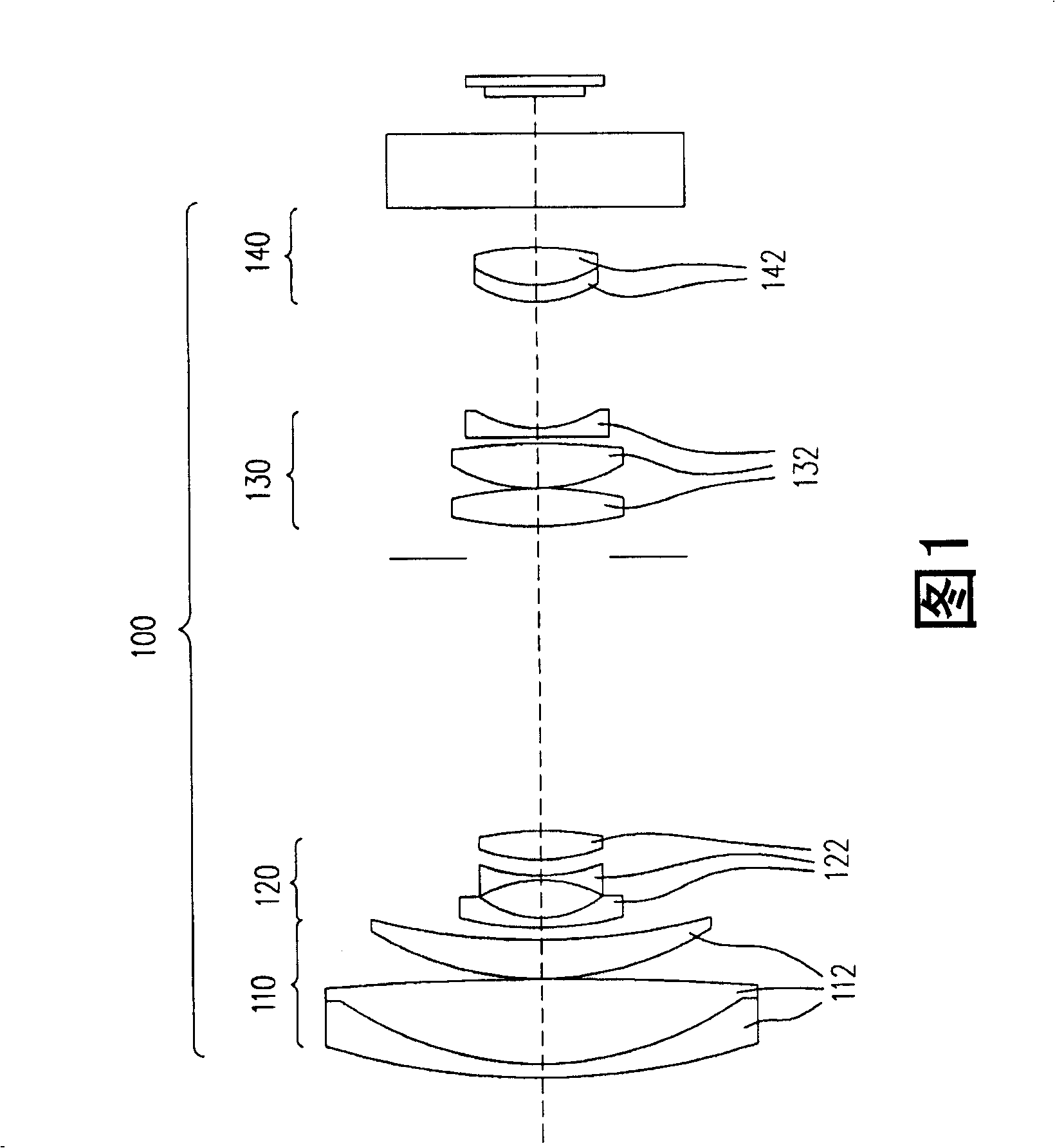
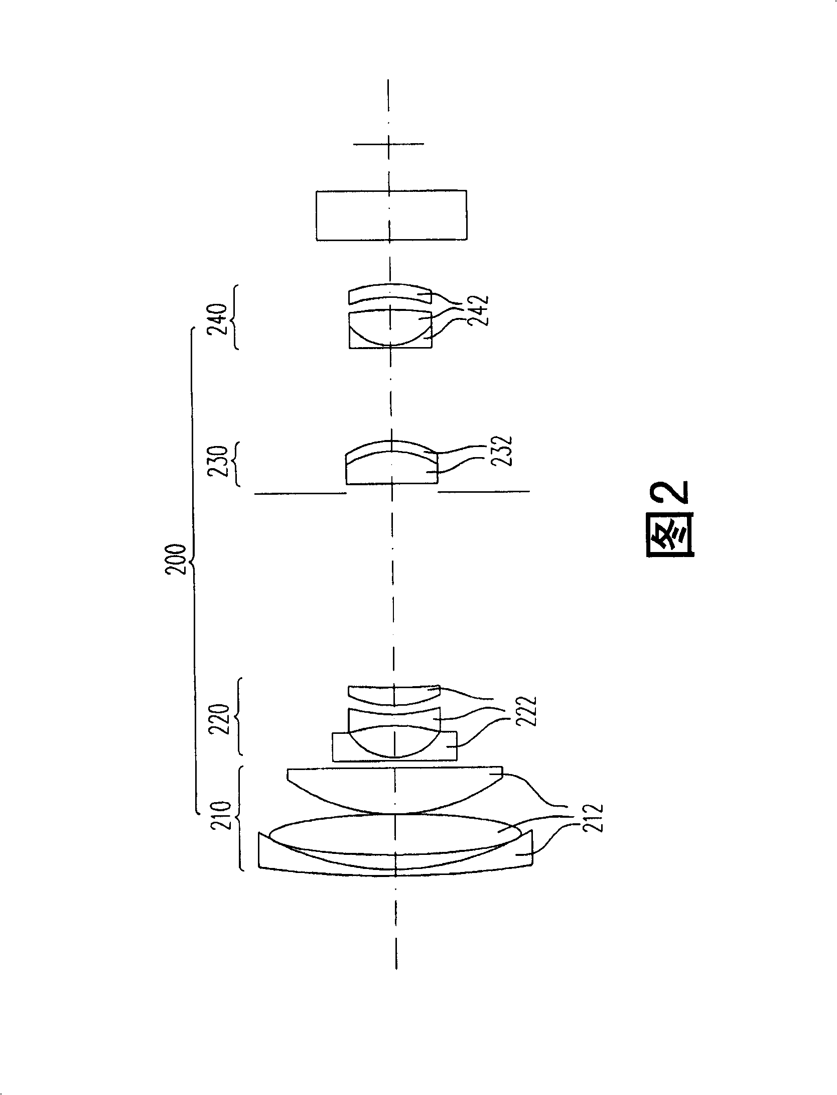
However, the linkage structure of the three lens groups 220, 230, 240 is relatively complicated in mechanism design, which easily makes the overall mechanism too large
In addition, due to the large number of movable lens groups, the requirements for the assembly tolerance of each lens must be more stringent to ensure the optical quality of the zoom lens 200, which will increase the production cost of the zoom lens 200

Method used


Image

  • Zoom lens
  • Zoom lens
  • Zoom lens

Examples


Embodiment Construction

[0017] The following descriptions of the various embodiments refer to the accompanying drawings to illustrate specific embodiments in which the invention may be practiced. The direction terms mentioned in the present invention, such as "up", "down", "front", "rear", "left", "right", etc., are only referring to the directions of the drawings. Accordingly, the directional terms are used to illustrate, not to limit, the invention.

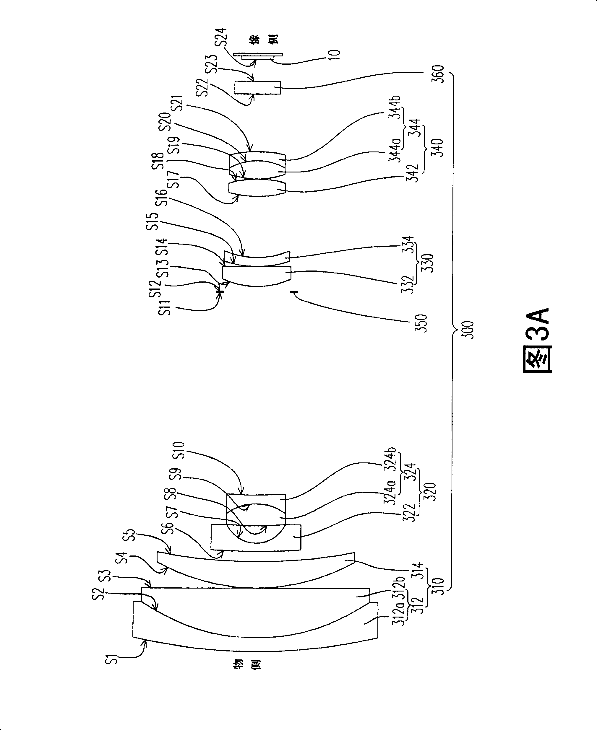
[0018] 3A to 3C are schematic diagrams of the structure of the zoom lens according to an embodiment of the present invention at different zoom ratios, wherein FIG. 3A shows the structure of the zoom lens at the wide-end (wide-end), and FIG. 3B shows the structure of the zoom lens at the middle position (middle), and Fig. 3C shows the structure when the zoom lens is at the tele-end (tele-end). 3A to 3C, the zoom lens 300 of this embodiment is suitable for imaging a scene located on an object side to an image side, wherein the image side can be configu...


PUM


Abstract

The invention relates to a zoom lens, comprising a first lens group, a second lens group, a third lens group and a fourth lens group arranged in sequence from an object side to an image side, wherein, the second lens group is suitable to move between the first lens group and the third lens group, and the fourth lens group is suitable to move between the third lens group and the image side. In addition, the first lens group has positive refraction, and comprises at least one first composite lens. The second lens group has negative refraction, and comprises at least one second composite lens. Meanwhile, the second composite lens comprises at least one aspheric lens, wherein, the adhesive surface of one of the aspheric lens is a concave face, and the adhesive surface faces the object side. The third lens group has positive refraction, and comprises at least one aspheric lens. The fourth lens group has positive refraction, and comprises at least a pair of convex lenses and a third composite lens from the object side to the image side. The zoom lens has the advantages of high rate and compact size.

Description

technical field [0001] The present invention relates to a lens, and in particular to a zoom lens. Background technique [0002] With the advancement of modern television communication (video) technology, image devices such as digital video camera (DVC) and digital camera (DC) have been widely used. One of the core components in these image devices is a zoom lens. The optical zoom of the zoom lens can make the far and near images clearly focus on the charge coupled device (CCD) for imaging. Therefore, the optical quality of the zoom lens and Imaging quality is closely related. In the fiercely competitive market, various manufacturers are all committed to improving the quality of the zoom lens and reducing its production cost, so as to enhance the competitive advantage of the above-mentioned imaging devices. In addition, in order to meet the requirements of light, thin, short, and small imaging devices, various manufacturers are also working on improving the design of the zo...

Claims


Application Information

Patent Timeline
Patent Type & Authority Applications(China)
IPC IPC(8): G02B15/16G02B15/14G02B9/34
Inventor 王国权
Owner YOUNG OPTICS
Learn More