Method, system and device for media buffer

A multimedia subsystem and media technology, which is applied in the field of network communication, can solve the problems of inability to realize media caching and direct access, and achieve the effects of saving media provision time, optimizing media provision mechanism, and improving multimedia services

Inactive Publication Date: 2008-09-10
HUAWEI TECH CO LTD
View PDF0 Cites 13 Cited by
  • Summary
  • Abstract
  • Description
  • Claims
  • Application Information

AI Technical Summary

Problems solved by technology

Under such a network architecture, the user equipment or the application server cannot directly obtain the address of the network entity used for bearer transmission, that is, the network between the user equipment and the application server cannot be regarded as transparent, and the address of the media cache address, the media buffer is introduced into the NGN network, therefore, the media buffer cannot be realized by using the current method
[0013] In summary, the current method cannot implement media caching in the network environment of the IMS network environment

Method used


Image

  • Method, system and device for media buffer
  • Method, system and device for media buffer
  • Method, system and device for media buffer

Examples


Embodiment 1

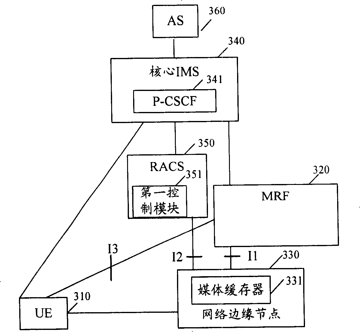
[0060] image 3 It is a schematic diagram of the system structure of the first embodiment of the present invention. The system in this embodiment includes a client user equipment (UE, User Equipment) 310 , an MRF 320 that provides media resources, and a network edge node 330 that sets a media cache 331 .

[0061] In this embodiment, a media cache 331 is set in the network edge node 330;

[0062] UE310 sends a service request to MRF320 through the core IMS, and sends a content request to MRF320 according to the service request response carrying the MRF address sent by MRF320 through the core IMS; for example, perform playback control operations such as fast forward, rewind, play, and pause, among which, Interface I3 is an interface between MRF320 and UE310, and this interface can use RTSP or a protocol with similar functions.

[0063] MRF320 obtains the information including the address of the media buffer, and sends a service request response carrying the address of the MRF ...

Embodiment 2

[0156] This embodiment provides a time-shifted TV-on-demand (TsTV) application example that realizes LTV content in a multicast mode. In the LTV stage of the TsTV service, what is buffered in the media buffer is the RTP message in the multicast message, that is, the cached content includes the RTP header. In this embodiment, a media buffer is set on a digital subscriber access multiplexer (DSLAM) of a network edge node, and the MRF is used as a playback control point. The schematic diagram of the system structure of this embodiment and image 3 Similar, the only difference is that the network edge node co-located with the media buffer is a DSLAM, and the network entity UPSF for verification is added, which will not be repeated here.

[0157] Figure 8 It is a schematic flow chart of the second embodiment of the present invention. In this embodiment, the content of the media buffer is provided from the DSLAM to the UE in a multicast manner. Whether the media buffer has conten...

Embodiment 3

[0201] Figure 9 It is a schematic diagram of the system structure of the third embodiment of the present invention. In this embodiment, it includes a client of a user equipment (UE, User Equipment) 910 , an MRF 920 and a media cache 931 set in a network edge node 930 .

[0202] This embodiment and image 3 In comparison, the main difference is that the MRF 920 provides the access side address of the media buffer 931 to the UE 920 through the core IMS, the media server in the MRF 920 executes the interface I4 between the module 921 and the media buffer 931, and the first The interface I5 between the control module 951 and the media buffer 931 and the interface I6 between the media buffer 931 and the UE 910 have new functional descriptions. The functional characteristics of these three interfaces are described in detail below.

[0203] The interface I4 is the interface between the MRF920 and the media buffer 931, and the media buffer 931 forwards the content request of the U...


PUM


Abstract

The invention provides a method for realizing media caching, which comprises the following steps: a media buffer is arranged; a client sends a service request to a media server MRF by a core IMS; the MRF obtains information including the address of the media buffer and sends a service request response including the MRF address or the address of the media buffer to the client by the core IMS; the client sends a content request to the MRF or the media buffer according to the received MRF address or the address of the media buffer; after receiving the content request sent by the client, the MRF or the media buffer provides content of request to the client. The invention also discloses systems corresponding to the two methods, which respectively comprise the client, the core IMS, the MRF and the media buffer. The invention also discloses two media buffers. The method for realizing media caching of the invention can realize media caching in an IMS network environment.

Description

technical field [0001] The present invention relates to the field of network communication, in particular to two methods, systems and devices for realizing media caching. Background technique [0002] At present, in systems that provide streaming media services based on IP networks, in order to improve service response speed and improve user service experience, media buffers (cache) are often set up near users. figure 1 It is a structural schematic diagram of an existing media cache. Wherein, the IP network 102 transparently connects the client 101 and the server 103, and the media cache 104 can cache part or all of the content of the server 103, and may be close to the client in physical location. When the client 101 requests related services, the media cache 104 104 can provide the stored data to the client 101 nearby, so that the average access time can be improved, the network transmission delay can be reduced, and at the same time, the bandwidth occupation of the core ...

Claims


Application Information

Patent Timeline
Patent Type & Authority Applications(China)
IPC IPC(8): H04L12/56H04L29/06H04L12/16H04N7/173H04L12/54
CPCH04L47/824H04L29/06217H04L65/4076H04L47/801H04L12/5695H04L29/06455H04L47/806H04L65/1016H04L47/722H04L47/70H04L65/611
Inventor 吴向阳严军
Owner HUAWEI TECH CO LTD
Why Eureka
Try Eureka