

Lock head adopting vane spring idle rotation lock master structure and the key thereof
A pincer and blade technology, applied in the field of mechanical locks, can solve problems such as difficult to guarantee processing accuracy, time-consuming processing, complex structure, etc., and achieve the effect of improving safety, reducing costs, and simple structure of the lock head
Active Publication Date: 2010-12-01
雷先鸣
View PDF1 Cites 0 Cited by
- Summary
- Abstract
- Description
- Claims
- Application Information
AI Technical Summary
Problems solved by technology
However, during the manufacturing process, it was found that there were still some problems in the lock head: the main reason was that the structure was complex, there were many parts, the processing was time-consuming, the processing accuracy was difficult to guarantee, and the cost was high
Method used
View moreImage
Smart ImageViewing Examples

Examples
Embodiment Construction
Login to View More PUM
 Abstract
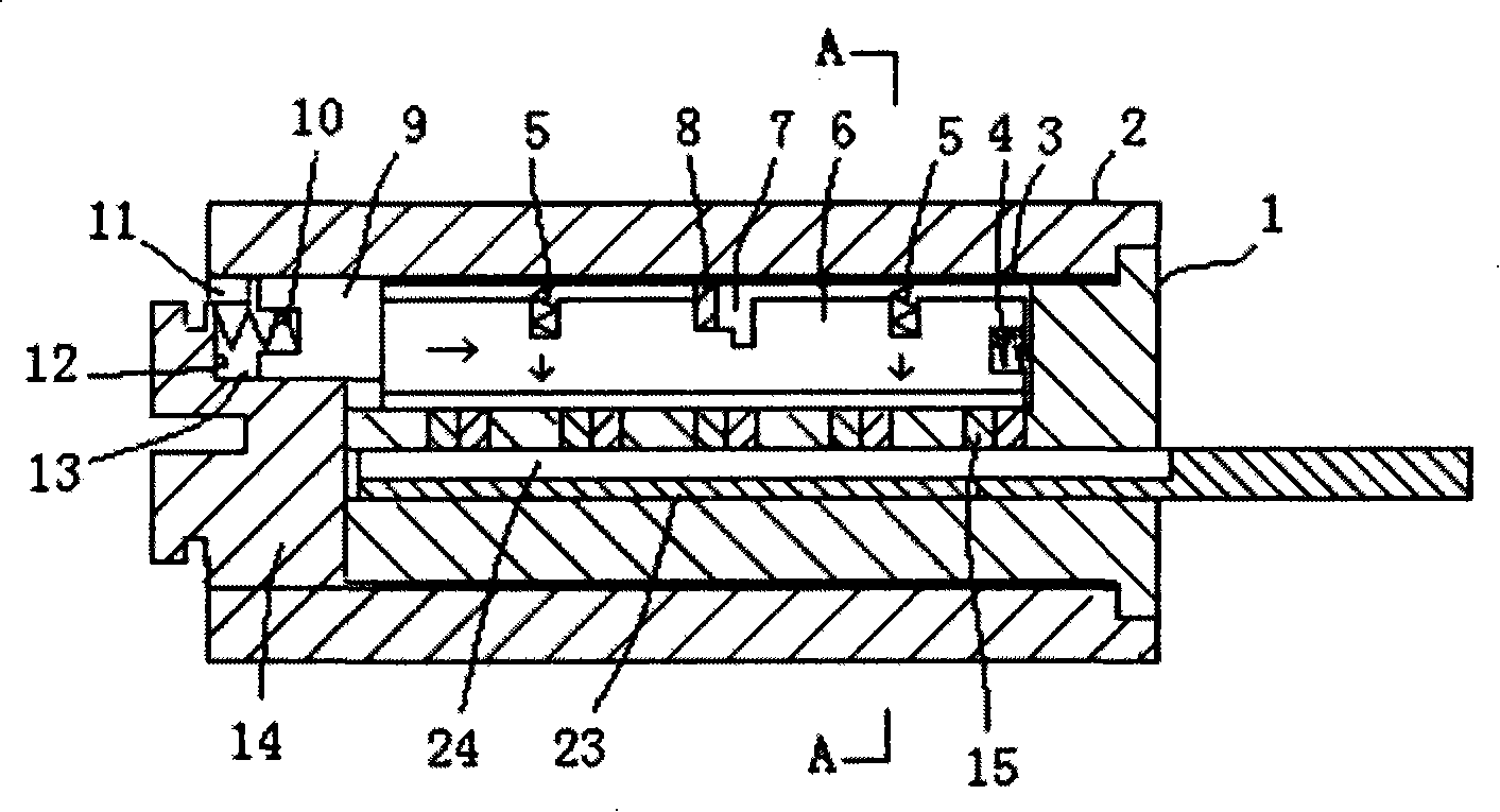
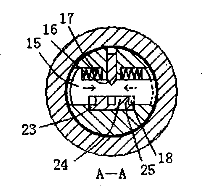
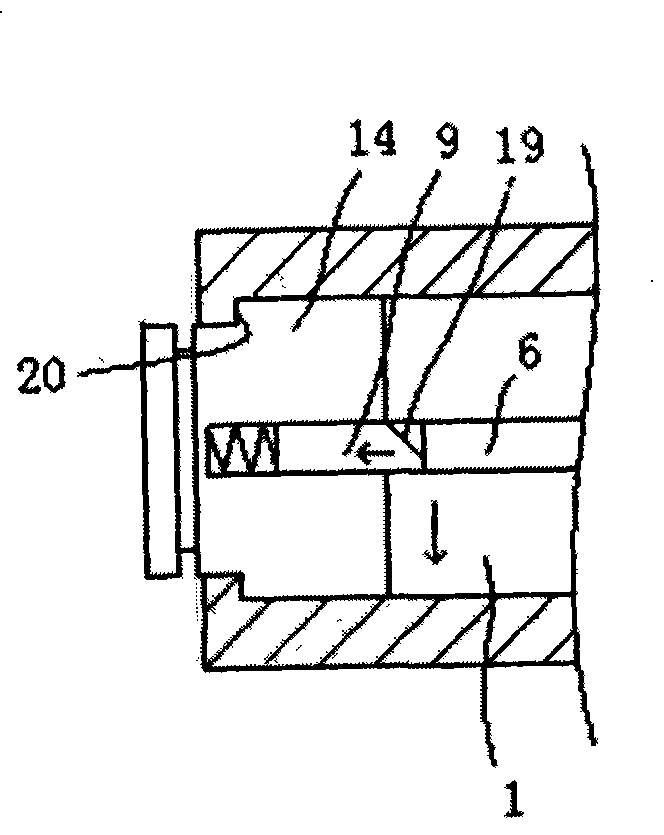
The invention discloses a lock with a leaf pin idling lock core structure, which comprises a front lock core in the lock body. A plurality of leaf pins are arranged along the axis on the front lock core, locking side posts matching with a V-shaped groove on the leaf pins are arranged in the locking side post grooves thereon, step-shaped grooves are provided on the locking side post, clamping plates and fixing parts matching with the step-shaped groove on the locking side post are arranged in the upper part of the locking side post. A radial return spring of the locking side post is arranged between the fixing parts and the locking side posts. The middle part on one side of the leaf pin is provided with a protruding part matching with the boss with the bits on the key. Only one side of thekey is provided with the boss of a thinner thickness. The lock of the invention has simple structure, less components and easy processing, and is capable of preventing a thicker tool from being inserted in a lock hole for violent unlocking.
Description
Lock head and key with blade pin idling lock cylinder structure technical field The invention belongs to mechanical locks, and relates to a lock head and a key with a blade pin idling lock cylinder structure. Background technique Chinese Patent No. ZL200710035717.X discloses a lock head whose lock cylinder can rotate idly. This lock head includes a lock body and a lock cylinder in the lock body. The lock cylinder is divided into a front lock cylinder and a rear lock cylinder. The locking side column and the sliding block, the sliding block and the locking side column are respectively provided with a protrusion (groove) and a groove (protrusion) that can be matched, and a locking side column return spring is provided between the locking side column and the sliding block , a sliding block return spring is provided between the sliding block and the end wall of the locking side column groove; a lock pin chute is arranged on the rear lock cylinder corresponding to the locking ...
Claims
Login to View More Application Information
Patent Timeline
 Patent Type & AuthorityPatents(China)
IPC IPC(8): E05B29/06E05B19/00
Inventor雷先鸣
Owner雷先鸣