Gear drive turbine compressor
A turbo compressor, gear-driven technology, applied in the direction of machines/engines, liquid fuel engines, mechanical equipment, etc., can solve the problems of damage to the impeller and casing, overheating, excessive contact between the impeller and the casing, etc., to reduce the possibility, Effect of preventing stirring loss
- Summary
- Abstract
- Description
- Claims
- Application Information
AI Technical Summary
Problems solved by technology
Method used
Image

Examples
Embodiment Construction
[0045] Below, preferred embodiments of the present invention will be described with reference to the accompanying drawings. In each figure, the same reference numerals are given to the same parts, and repeated explanations will be omitted.
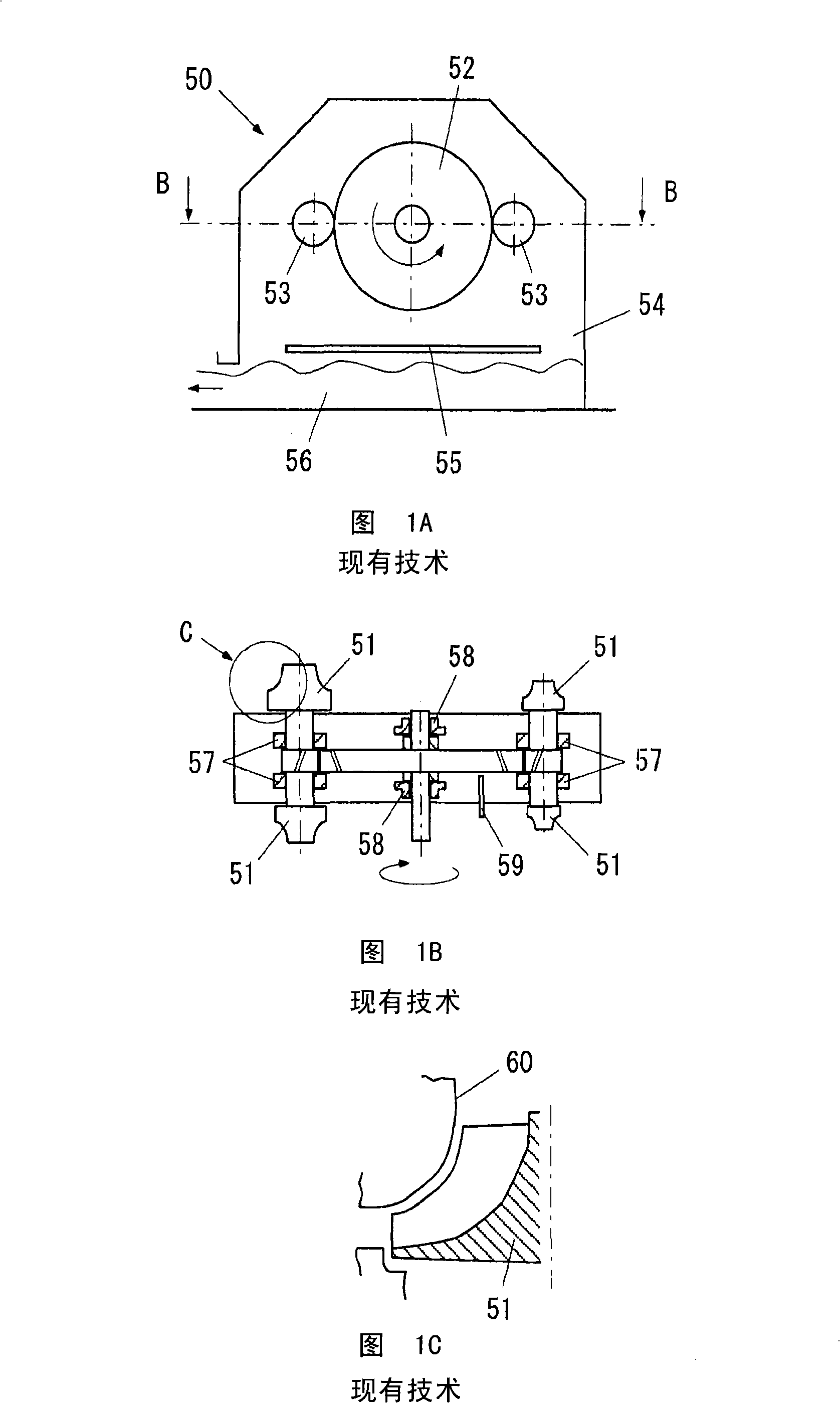
[0046] Figure 4It is a partial sectional view of the gear-driven turbo compressor provided by the present invention corresponding to FIG. 1B . In this figure, the gear driven turbo compressor 10 of the present invention has a bull gear 12 , a pinion gear 14 , an impeller 16 , a thrust ring 18 and a thrust bearing 20 .
[0047] In this figure, the gear-driven turbo compressor 10 of the present invention is a 4-stage compressor, but the present invention is not limited thereto, it can be a single-stage compressor, or a compressor with 2, 3 or 5 or more stages. machine.
[0048] The bull gear 12 is driven to rotate around the axis of the bull gear shaft 11 by an unshown external drive device (an electric motor, an engine, or a turbine). T...
PUM
 Abstract
Description
Claims
Application Information
 - Generate Ideas
- Intellectual Property
- Life Sciences
- Materials
- Tech Scout
- Unparalleled Data Quality
- Higher Quality Content
- 60% Fewer Hallucinations
Browse by: Latest US Patents, China's latest patents, Technical Efficacy Thesaurus, Application Domain, Technology Topic, Popular Technical Reports.
© 2025 PatSnap. All rights reserved.Legal|Privacy policy|Modern Slavery Act Transparency Statement|Sitemap|About US| Contact US: help@patsnap.com