Eureka AIR delivers breakthrough ideas for toughest innovation challenges, trusted by R&D personnel around the world.

Push electric magnet

Inactive Publication Date: 2008-09-17
王万年
View PDF0 Cites 2 Cited by
  • Summary
  • Abstract
  • Description
  • Claims
  • Application Information

AI Technical Summary

Problems solved by technology

In pharmaceutical, food, printing, tobacco and other industries, the flow speed of products on high-speed production lines is very fast. The push-type electromagnet in the prior art still has a lot of residual magnetism on the moving iron after the power is cut off, so the reaction speed is relatively slow. It is difficult to achieve the accuracy of product control on high-speed production lines

Method used


Image

  • Push electric magnet

Examples


Embodiment Construction

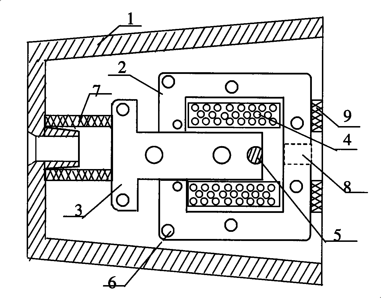
[0008] The implementation of the present invention will be described below in conjunction with the accompanying drawings. Depend on figure 1 It can be seen that the push electromagnet provided by the present invention is composed of an electromagnet housing 1, a static iron 2, a moving iron 3 and an electromagnetic coil 4, and a soft magnetic metal strip 5 is inlaid at the head end of the moving iron 3. When the electromagnetic coil 4 is energized, the strong magnetic field generated by the electromagnetic coil 4 and the static iron 2 surrounding the electromagnetic coil will attract the moving iron 3 into the space surrounded by the static iron 2 and the electromagnetic coil 4, and hit the rear part of the electromagnet for execution. The spring and push rod of the mechanism make the actuator complete the production work. Due to the effect of the soft magnetic metal strip 5 inlaid at the head end of the moving iron 3, the residual magnetism on the moving iron is very little ...


PUM


Abstract

The invention belongs to a device element of the electric field, relating to a pushing type electromagnet. The pushing type electromagnet is composed by a shell, an immovable iron, a movable iron and an electromagnetic coil, characterized in that a soft magnetic metal bar is inlayed at a head end part of the movable iron. When the electromagnetic coil is electrified, the electromagnetic coil and the immovable iron surrounding the electromagnetic coil generate powerful suction of magnetic field to suck the movable iron into a space surrounded by the immovable iron and the electromagnetic coil, in order to impact a spring and a push rod of a rear part executing mechanism of an electromagnet so that the executing mechanism completes the production; when the electromagnetic coil is broken off, due to the effect of the soft magnetic metal bar inlayed at the head end part of the movable iron, remanence of the movable iron of the pushing type electromagnet is almost zero, the spring and the push rod of the rear part executing mechanism of the electromagnet resets rapidly under the influence of the movable iron, the response speed is quite fast and movement frequency of the electromagnet is accelerated, so the pushing type electromagnet is applicable for the working demands of automatic control in high-speed product line and improves the working efficiency of the automatic product line.

Description

technical field [0001] The invention belongs to an electrical component in the field of electricity, and relates to a push type electromagnet. Background technique [0002] An electromagnet is an electrical component that converts electrical energy into mechanical energy for linear motion. Its characteristics are: the structure of the linear motion is simpler than that of the motor plus the conversion mechanism, the cost is low, the noise is small, and the life is long. Utilizing the presence or absence of the magnetism of the electromagnet, it can be controlled by the current on and off; the magnitude of the magnetism can be controlled by the strength of the current or the number of turns of the coil. In the field of product packaging in the automated production line, a large number of electromagnets are used to control Perform production control. The currently widely used push electromagnet consists of a shell, a static iron, a moving iron and an electromagnetic coil. Whe...

Claims


Application Information

Patent Timeline
Patent Type & Authority Applications(China)
IPC IPC(8): H01F7/06
Inventor 王万年陈德芳
Owner 王万年
Why Eureka
Eureka Blog
Learn More