Switch

A switch and switch body technology, applied in the field of switches, can solve the problems of shortening the size in the arrangement direction, and achieve the effect of miniaturization and reliability.

Active Publication Date: 2008-09-17
ORMON CORP
View PDF1 Cites 9 Cited by
  • Summary
  • Abstract
  • Description
  • Claims
  • Application Information

AI Technical Summary

Problems solved by technology

Therefore, in order to detect the proximity of the magnets 30-1, 30-2 at a certain detection distance with the Hall ICs 31-1, 31-2, it is necessary to make the distance between adjacent magnets 30-1, 30-2 greater tha

Method used


Image

  • Switch
  • Switch
  • Switch

Examples


Embodiment Construction

[0039] Hereinafter, embodiments of the present invention will be described in detail with reference to the drawings.

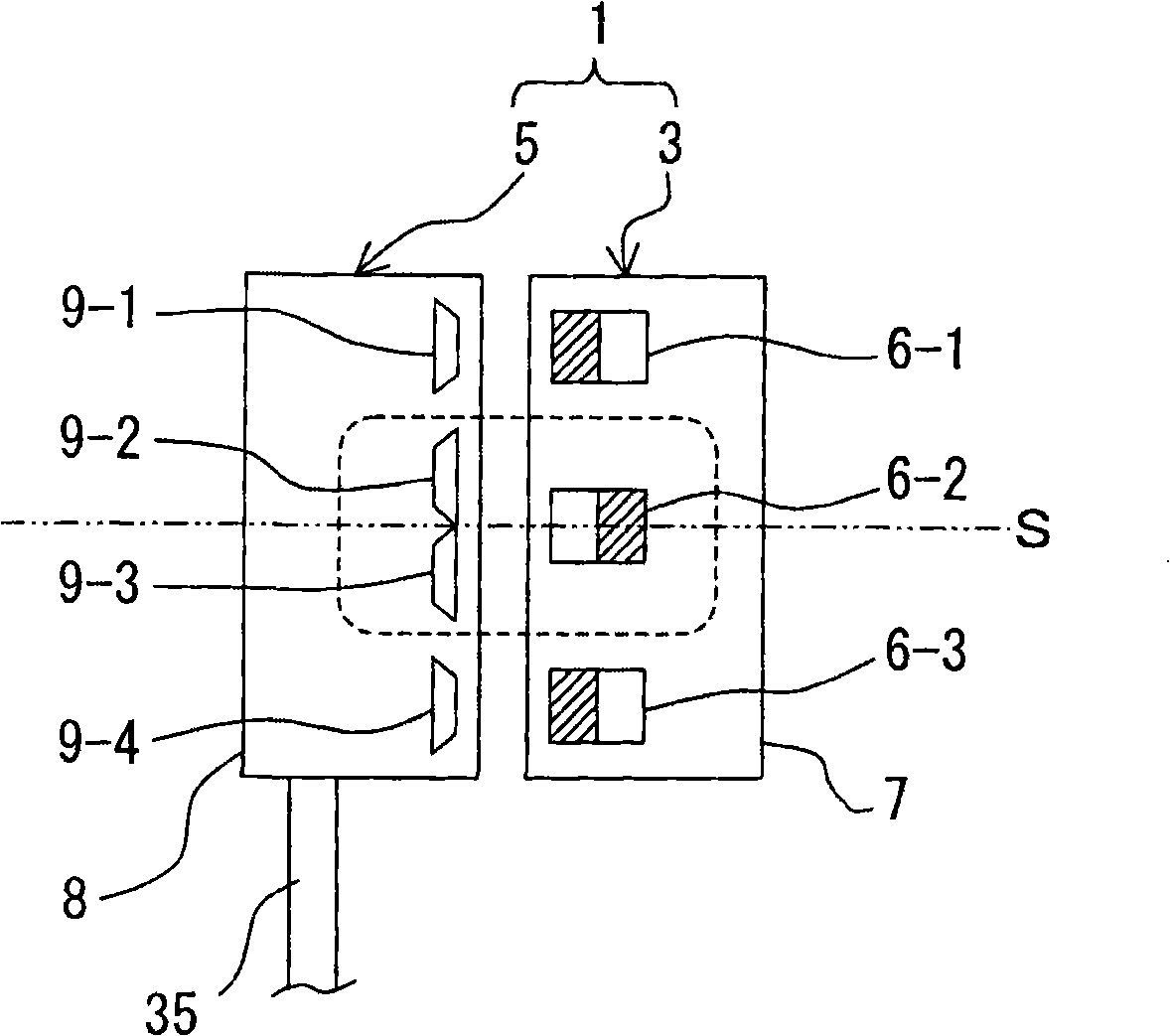
[0040] figure 1 It is a schematic configuration diagram of a proximity switch according to an embodiment of the present invention.

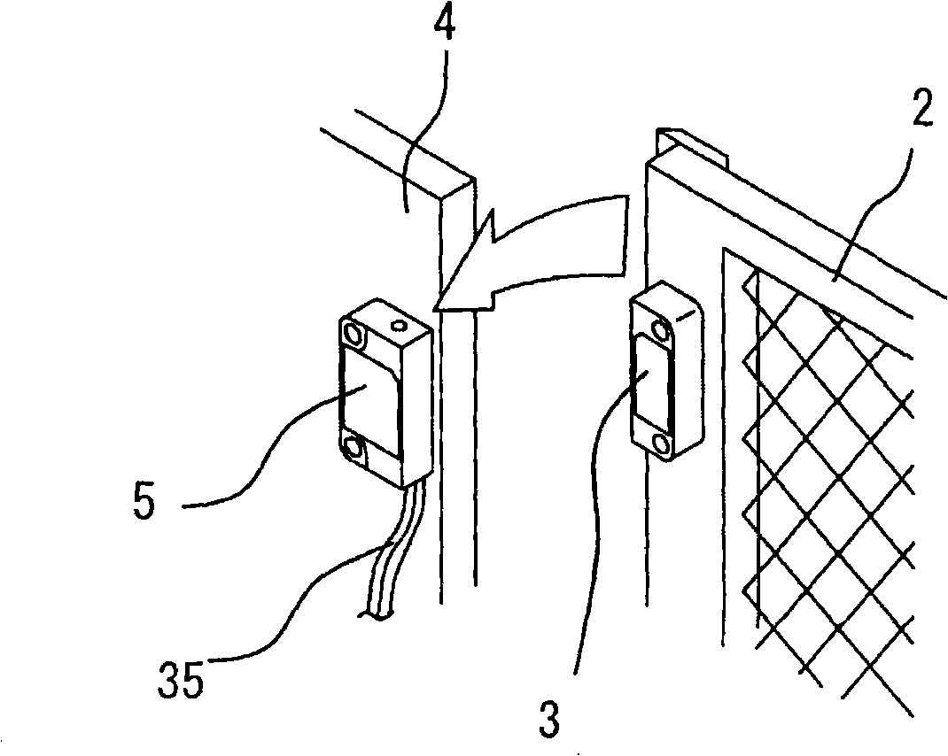
[0041] The switch 1 is used for example as figure 2 The door switch of the shown safety door has an actuator 3 and a switch body 5, wherein the actuator 3 is used as a working part installed on one side of the door 2 that is opened and closed as shown by the arrow, and the switch body 5 Installed on the side of the fixed frame 4 of the door, it is used to detect the approach or departure of the actuator 3, that is, the opening and closing of the door 2.

[0042] In this embodiment, if figure 1 As shown, three magnets 6 - 1 to 6 - 3 are arranged in a row at equal intervals along the length direction of the housing 7 (the up-and-down direction in the figure) and are accommodated in the housing 7 of the actuator 3 .

[0043] ...


PUM


Abstract

The invention provides a non-contact switch which can ensure reliability and realize miniaturization. A central magnet (6-2) of a plurality of magnets (6-1 to 6-3) arranged to be different in polarities is detected by two hall (IC9-2,9-3); therefore, reduction in size can be achieved by reducing the number of the magnets; and at the same time, the number of the hall ICs can be maintained and the reliability can be secured, as compared with a configuration in which the magnets and the hall ICs individually respond in one to one correspondence.

Description

technical field [0001] The present invention relates to a switch, and more particularly, to a non-contact switch using a magnetic sensor. Background technique [0002] Since the non-contact switch has no mechanical contacts, there is no wear between the contacts, and it has excellent durability and does not generate abrasion powder, etc., so it is suitable for food and semiconductors. For example, Patent Document 1 describes a door switch that detects the opening and closing of the door of a dedicated refrigerator that is frequently opened and closed based on the proximity or distance between a magnet and a Hall integrated circuit (Hall integrated circuit: Hall integrated circuit). . [0003] Patent Document 1: JP Unexamined Patent Application Publication No. 2005-326058 [0004] High reliability is required when a non-contact switch is used, for example, as a door switch of a safety gate used to enter and exit a working area defined by safety barriers around mechanical eq...

Claims


Application Information

Patent Timeline
IPC IPC(8): H03K17/95G01V3/08
CPCH03K17/9502H03K17/9515H03K17/97H01H36/008H01H36/02
Inventor 中山晃行桥本实井手孝浩
Owner ORMON CORP
Why Eureka
Try Eureka