Scroll compressor

A scroll compressor and compressor technology, applied in the direction of rotary piston machinery, rotary piston pump, mechanical equipment, etc., can solve the problems of performance degradation, friction power consumption increase, etc., achieve contact force optimization, reduce friction work Consumption, performance-enhancing effect

Inactive Publication Date: 2008-09-24
MIDEA GRP CO LTD
View PDF0 Cites 7 Cited by
  • Summary
  • Abstract
  • Description
  • Claims
  • Application Information

AI Technical Summary

Problems solved by technology

Since the axial contact force will cause sliding friction between the non-orbiting scroll and the orbiting scroll on the end plate surface, then, when the axial contact force is too large, the friction power consumption will increase a lot, resulting in a decrease in performance

Method used


Image

  • Scroll compressor
  • Scroll compressor
  • Scroll compressor

Examples


Embodiment Construction

[0024] The present invention will be further described below in conjunction with the accompanying drawings and preferred embodiments.

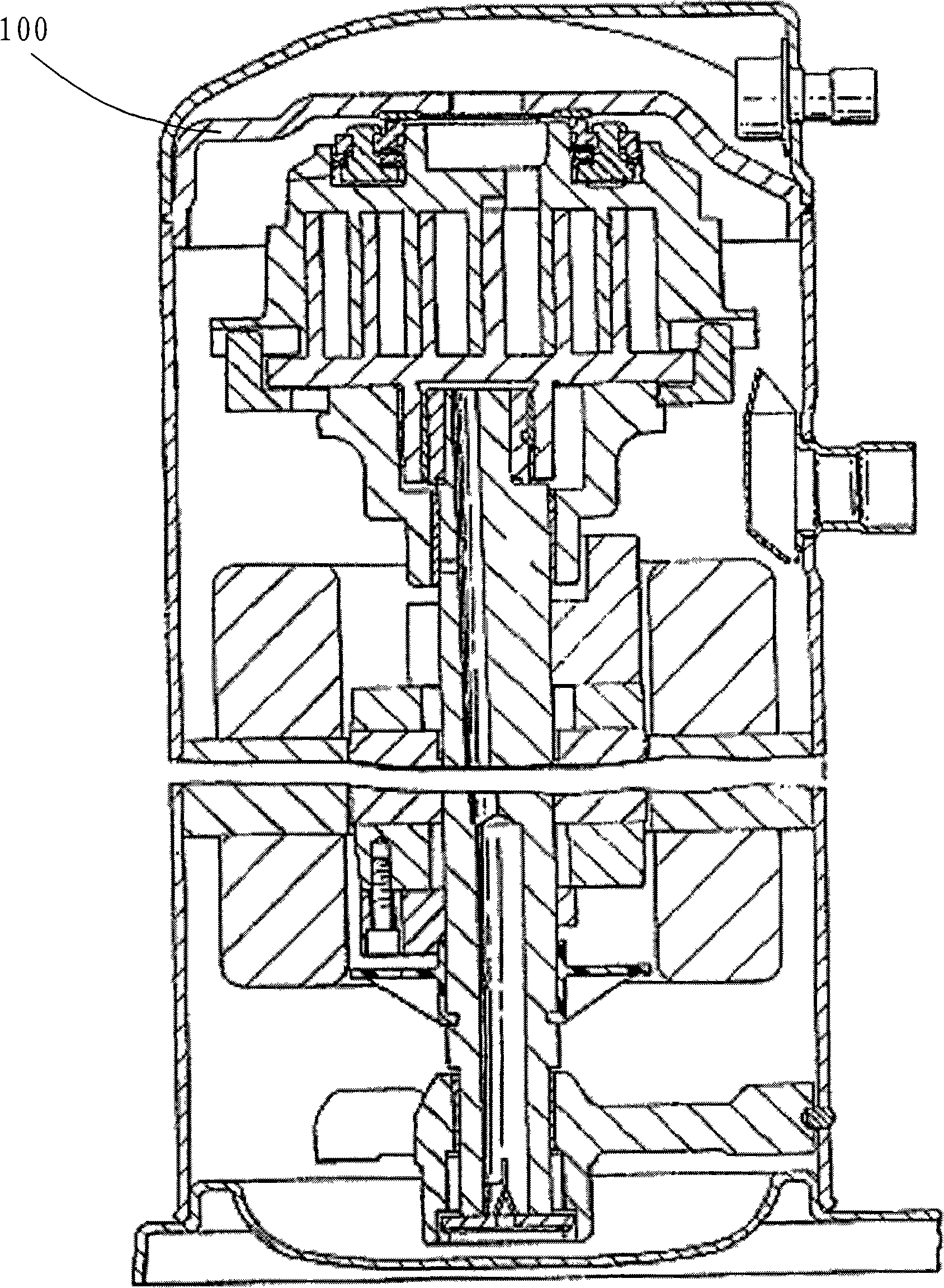
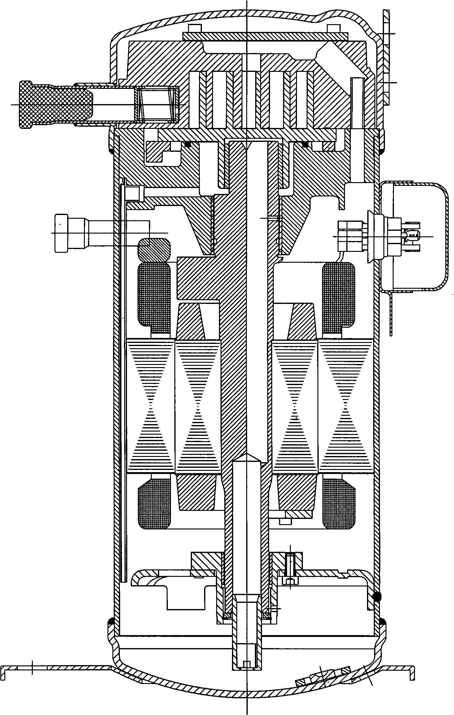
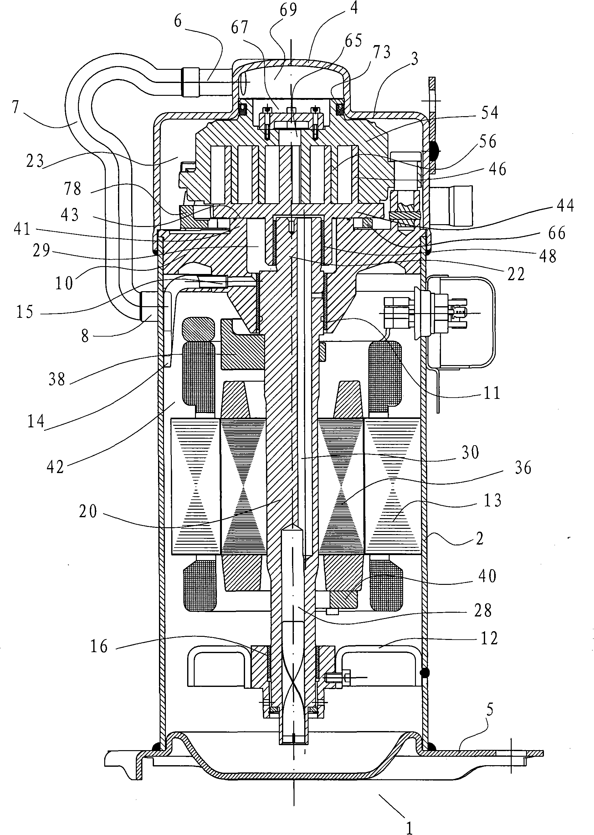
[0025] See attached image 3 , the shell of the scroll compressor 1 includes a generally cylindrical main shell 2, the upper part of the main shell is welded with an upper shell 3, and the middle of the upper shell protrudes outward to form a cup-shaped The concave part 4. A base 5 is welded to the lower part of the main housing, and a plurality of mounting feet are installed on the base, which are not shown in the figure. An upper gas guide joint 6 for refrigerant is installed on the recess 4 of the upper housing, and a lower air guide joint 8 is also installed on the main housing. One end of the exhaust pipe 7 is installed in the upper air guide joint 6, and the other end is installed in the lower guide Gas connector 8. Other main components fixed on the main housing include: frame 10, which is suitably fixed on the main housing; The leg...


PUM


Abstract

The invention relates to a scroll compressor which includes a non-revolution vortex part and a revolution vortex part. An elastic deadening cavity for discharging air consists of a driving shaft which is supported by the bearing of a frame, the back lateral of the non-revolution vortex part and an upper casing commonly. The back lateral of the non-revolution vortex part is pressed to be in contact with the inner wall of the deadening cavity through a sealing component in a way of sliding. The deadening cavity is communicated with an air discharging cavity which is arranged on a motor side on the lower part of the compressor and is formed by a frame, a main casing and a sealing part in a way of sealing. The design optimizes the contact force between the non-revolution vortex part and the revolution vortex part and between the revolution vortex part and the frame in the maximal degree. The non-revolution vortex part under the pressure function of high-pressure gas in the deadening cavity on the back lateral of the non-revolution vortex part and the revolution vortex part under the pressure function of high-pressure fluid on the back lateral of the revolution vortex part are in closely contact with each other and are sealed axially. The non-revolution vortex part is arranged on an installation mechanism in a way of sliding upwards and downwards and can move axially within a certain range.

Description

technical field [0001] The invention relates to a scroll compressor, in particular to a scroll compressor that allows a certain axial displacement of a non-revolving scroll. Background technique [0002] Existing scroll compressors include a non-revolving scroll with a scroll crimp on the bottom plate and an orbiting scroll with a scroll curl on the end plate, and the two scrolls face each other Meshing configurations compress fluid entering a scroll compressor by sequentially constricting a plurality of compression chambers formed between mutual curls. During the compression process, the fluid generates an axial force that separates the orbiting scroll and the non-orbiting scroll from each other, resulting in the axial separation of the orbiting scroll and the non-orbiting scroll. Leaks will occur after large gaps appear between them. [0003] For scroll compressors with high-pressure exhaust pressure on the motor side, the current technology generally adopted by manufact...

Claims


Application Information

Patent Timeline
Patent Type & Authority Applications(China)
IPC IPC(8): F04C29/00F04C15/00F04C18/02F04C2/02
Inventor 邵海波
Owner MIDEA GRP CO LTD
Why Eureka
Try Eureka