Eureka AIR delivers breakthrough ideas for toughest innovation challenges, trusted by R&D personnel around the world.

Microcurrent controlled capillary tube electrophoresis liquid core waveguide fluorescence testing apparatus

A technology of capillary electrophoresis and liquid core waveguide, which is applied in the field of microfluidic analysis, can solve the problems of less application and research of microfluidic analysis instruments, and achieve the effects of fast speed, high sensitivity, and reduced use of optical components

Inactive Publication Date: 2010-04-14
NORTHEASTERN UNIV LIAONING
View PDF5 Cites 5 Cited by
  • Summary
  • Abstract
  • Description
  • Claims
  • Application Information

AI Technical Summary

Problems solved by technology

However, there are still few applications in simplifying the optical system and miniaturizing microfluidic analysis instruments.

Method used


Image

  • Microcurrent controlled capillary tube electrophoresis liquid core waveguide fluorescence testing apparatus
  • Microcurrent controlled capillary tube electrophoresis liquid core waveguide fluorescence testing apparatus
  • Microcurrent controlled capillary tube electrophoresis liquid core waveguide fluorescence testing apparatus

Examples


Embodiment Construction

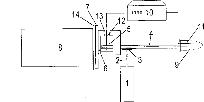
[0018] attached figure 1 It is a structural schematic diagram of a microfluidic capillary electrophoresis liquid core waveguide fluorescence detection device in a preferred embodiment of the present invention. The photodetector 8 is a photomultiplier tube, and its optical signal receiving end is a shading plate 14. The shading plate 14 is a black plastic with a thickness of 0.5 mm. Sheet; Shading plate 14 is close to optical filter 7, and optical filter 7 is the long wave pass optical interference filter of cut-off wavelength 560 nanometers; Optical filter 7 is close to reservoir 5, the reservoir wall of reservoir 5 6. The material is glass with a thickness of 0.5 mm. The liquid storage tank wall 6 and the liquid storage tank 5 are bonded together with epoxy resin glue. Brush black paint, the place that is not painted black is used as the transparent light window that transmits fluorescence; Insert the outlet end of the liquid-core waveguide capillary 4 in the liquid reservoir...


PUM

PropertyMeasurementUnit
thicknessaaaaaaaaaa
thicknessaaaaaaaaaa
diameteraaaaaaaaaa

Abstract

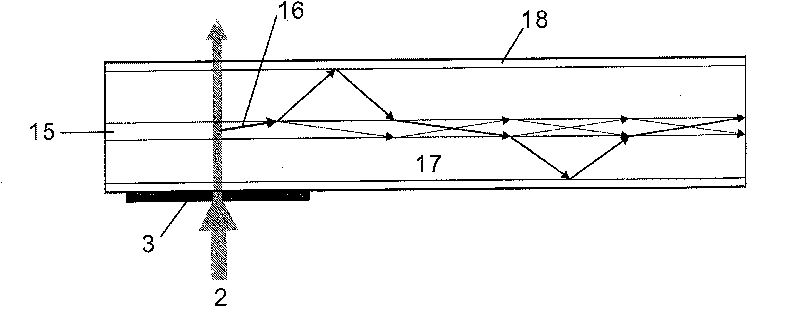
A micro flow control capillary electrophoresis liquid core waveguide fluorescence detector includes a liquid core waveguide capillary, a laser light source, a photodetector, a high-voltage power supply, an electrode, a liquid storage container, a sample tube, a pinhole diaphragm, a filter and a shadow shield; the device makes use of a liquid core waveguide phenomenon and uses the same liquid corewaveguide capillary as a capillary electrophoresis separation channel and for fluorescence signal transduction. In the invention, the light given out by the laser light source can be not focused by alens but directly radiates on the liquid core waveguide capillary through the pinhole diaphragm; the fluorescence led out by the outlet port of the liquid core waveguide capillary can not be collectedbythe lens but directly enters into the photodetector through the filter. The liquid core waveguide capillary is taken as a micro flow control capillary electrophoresis separation channel and an optica l conduction channel, so as to furthest reduce optical elements, simplify an optical system, make the structure more compact, so as to provide a feasible technical route for developing miniature microflow control analytical instruments.

Description

technical field [0001] The invention belongs to the technical field of microfluidic analysis, in particular to a microfluidic capillary electrophoresis liquid core waveguide fluorescence detection device. Background technique [0002] Microfluidics (or microfluidics) is the technology and science of manipulating nanoliter (n1) to picoliter (p1) volume fluids in micron-scale structures [Fang Zhaolun, Fabrication and Application of Microfluidic Analysis Chip, Chemistry Industrial Press, 2005, 4]. Microfluidic analysis with microfluidics as the core technology has become the forefront of the development of contemporary analytical science. Microfluidic analysis has obvious advantages such as fast analysis speed, less consumption of samples and reagents, high degree of integration, and small volume, and has gradually played an important role in chemical and biological testing. [0003] The miniaturization of the analysis system puts forward corresponding requirements for the de...

Claims


Application Information

Patent Timeline
Patent Type & Authority Patents(China)
IPC IPC(8): G01N21/64
Inventor 徐章润樊晓峰王世立方肇伦
Owner NORTHEASTERN UNIV LIAONING
Why Eureka
Eureka Blog
Learn More