
Method, system and device for controlling data flux

A flow control and flow technology, which is applied in the field of network communication, can solve the problems of data frame loss, FU buffer overflow, and the switching network device does not have the scheduling function, so as to avoid data frame loss and ensure QoS.

Active Publication Date: 2008-09-24
NEW H3C TECH CO LTD
View PDF0 Cites 25 Cited by
  • Summary
  • Abstract
  • Description
  • Claims
  • Application Information

AI Technical Summary

Problems solved by technology

[0005] However, the switching network device using this non-fixed-length switching method does not have a scheduling function, and cannot control the flow of data frames sent by each VOQ to the FU, which may cause the FU buffer to overflow and cause the loss of data frames
That is to say, the prior art cannot guarantee the service quality (QoS, Quality of Service) of the data exchange business

Method used


Image

  • Method, system and device for controlling data flux
  • Method, system and device for controlling data flux
  • Method, system and device for controlling data flux

Examples


Embodiment Construction

[0029] In order to make the object, technical solution and advantages of the present invention clearer, the present invention will be described in detail below in conjunction with the accompanying drawings and specific embodiments.

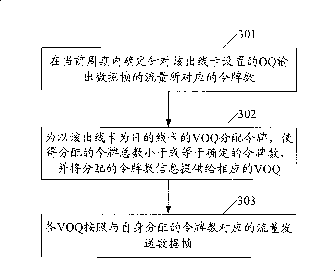
[0030] At first the method provided by the invention is described, image 3 The flow chart of the main method provided by the embodiment of the present invention, in this embodiment, each VOQ can be assigned a token initially, so that in an initial cycle, the flow of all VOQ output data frames and the flow of all OQ output data frames The difference of is less than or equal to the FU buffer, wherein each VOQ outputs data frames according to the traffic corresponding to the number of tokens allocated to it in the initial cycle. like image 3 As shown, perform the following steps periodically for each outgoing line card:

[0031] Step 301: In the current cycle, determine the number of tokens corresponding to the flow of OQ output data frames set f...


PUM


Abstract

The invention provides a method, a system and a device for flux control and the steps as follows are carried out in connection with the periodicity of the outgoing cards: in the current period, the token number corresponding to the flux of the output data frame of an output queue (OQ) arranged in light of the outgoing line cards is confirmed; the tokens are distributed to a virtual output queue (VOQ) by taking the outgoing cards as targeted line cards, so that the total number of the tokens distributed is less than or equal to the confirmed token number; the data frames are sent out according to the flux corresponding to the self-distributed token number by the virtual output queue (VOQ). That is to say, by distributing the tokens, the method, the system and the device distribute the bandwidth output by an exchange network to the outgoing card to the bandwidth input by an ingoing line card to the exchange network, thus preventing the bandwidth of the input exchange network from exceeding the bandwidth output by the exchange network, avoiding data loss phenomenon caused by the buffer overflow of the core exchange unit (FU) of the exchange network and ensuring the quality of service (QoS) of the data exchange business.

Description

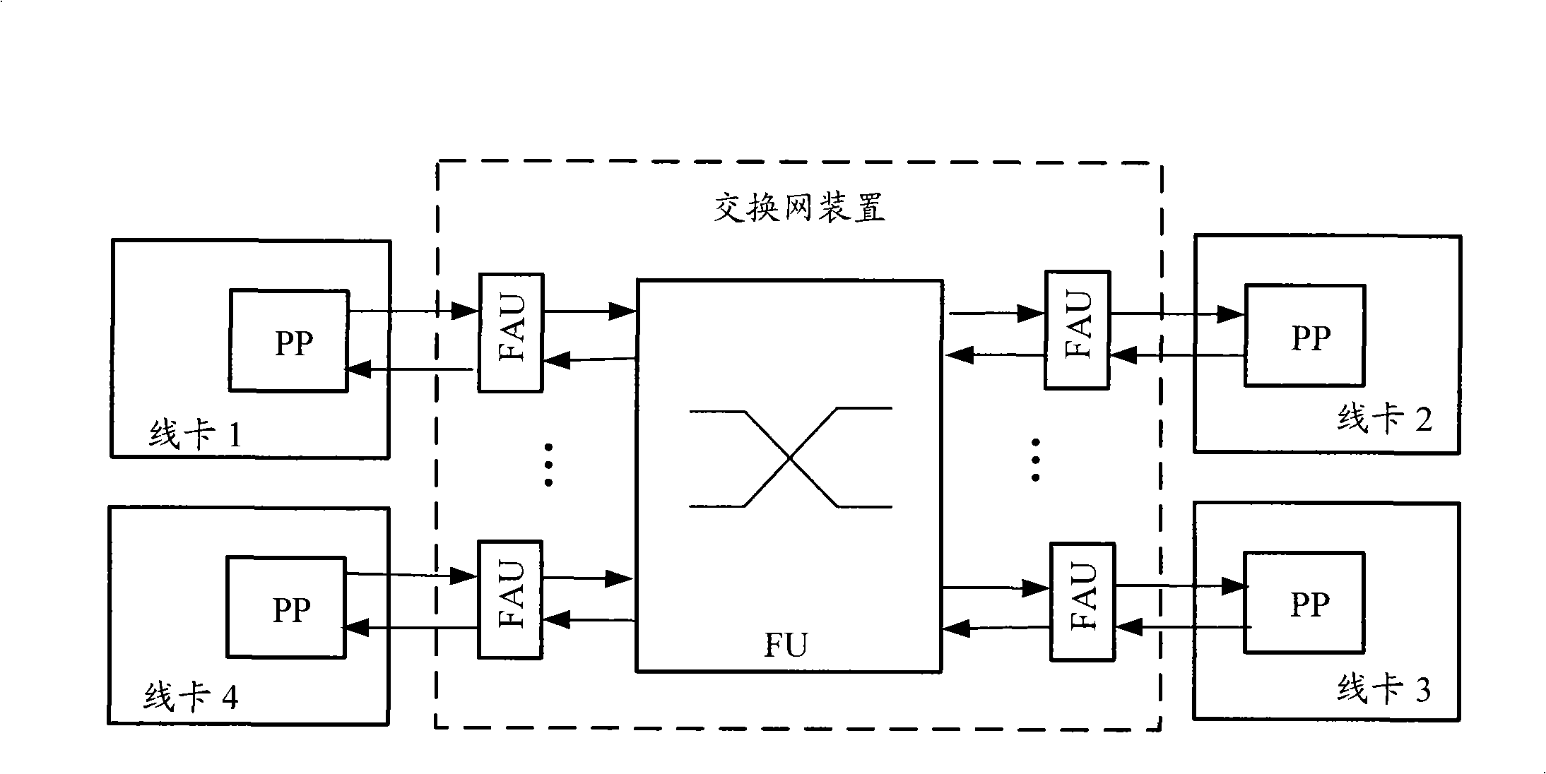
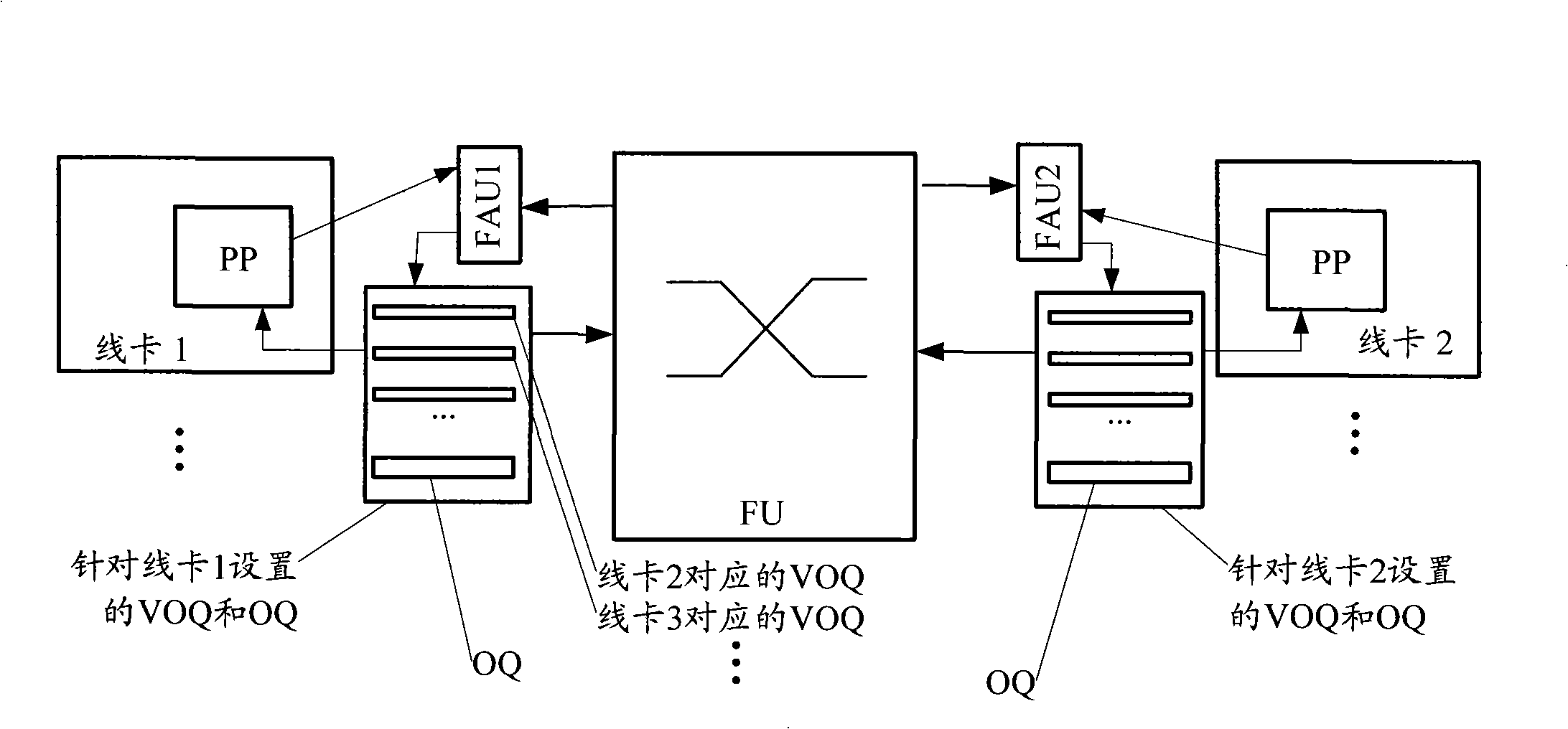
technical field [0001] The present invention relates to network communication technology, in particular to a flow control method, system and device. Background technique [0002] The switching network device is the core part of equipment such as modular routers and switches, and is responsible for data exchange between line cards at each port or slot. The composition of the existing switching network device is as follows: figure 1 As shown, the switching network device mainly includes a core switching unit (FU, Fabric Unit) and a switching access unit (FAU, FabricAccess Unit), each FAU is responsible for the connection between the FU and each line card, and the FU connects each line card through each FAU A Packet Processor (PP, Packet Processor) in is used to complete the data exchange between the line cards. Wherein, the FAU can be set on the line card, and the FU can be set on the switching fabric board. [0003] In order to reduce the cost of the switching network devi...

Claims


Application Information

Patent Timeline
Patent Type & Authority Applications(China)
IPC IPC(8): H04L12/56H04L12/851
Inventor 余昌刚
Owner NEW H3C TECH CO LTD
Learn More