Photon counting CT detector using solid-state photomultiplier and scintillator

A scintillator and detector technology, applied in the field of CT detector modules, can solve problems such as reduced fidelity, photon omission or mislabeling, etc.

Active Publication Date: 2008-10-01
GENERAL ELECTRIC CO
View PDF0 Cites 14 Cited by
  • Summary
  • Abstract
  • Description
  • Claims
  • Application Information

AI Technical Summary

Problems solved by technology

Charge sharing can cause photons to be missed entirely or mislabeled with energy
In either case, as a result of using subdivided pixels each connected to its own amplifier, the DQE drops and the spectral response will degrade fidelity

Method used


Image

  • Photon counting CT detector using solid-state photomultiplier and scintillator
  • Photon counting CT detector using solid-state photomultiplier and scintillator
  • Photon counting CT detector using solid-state photomultiplier and scintillator

Examples


Embodiment Construction

[0024] According to one aspect of the present invention, a CT imaging system is provided. CT imaging systems include detectors configured to perform photon counting and energy discrimination of high flux rates of x-rays typically associated with CT imaging.

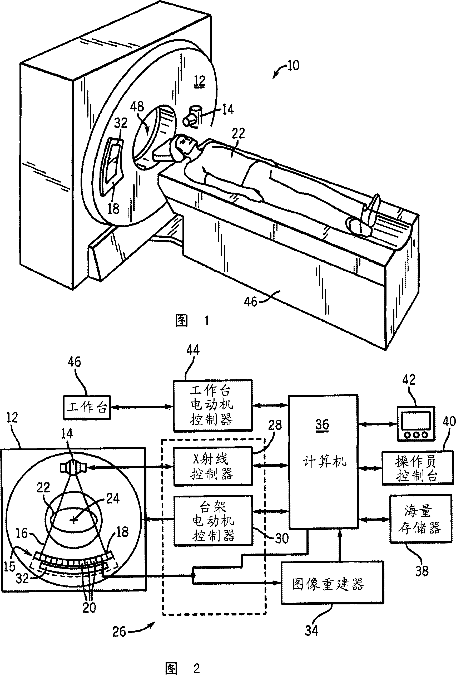
[0025] The operating environment of the present invention is described with reference to a sixty-four slice computed tomography (CT) system. However, those skilled in the art should know that the present invention is also applicable to other multi-chip structures. Furthermore, the invention will be described in connection with the detection and conversion of x-rays. However, those skilled in the art also know that the present invention is also applicable to the detection and conversion of other high-frequency electromagnetic energy. The invention will be described in connection with "third generation" CT scanners, but the invention is equally applicable to other CT systems.

[0026]Referring to Figures 1 and 2, a compu...


PUM


Abstract

A detector module for a CT imaging system includes a scintillator to convert x-rays to optical photons. The scintillator is optically coupled to a solid-state photomultiplier with internal gain to receive the optical photons and convert them into a corresponding electrical signal output.

Description

technical field [0001] The present invention relates generally to radiographic detectors for diagnostic imaging and, more particularly, to a CT detector module capable of providing photon count and energy data with improved saturation characteristics. Background technique [0002] Typically, in radiography (imaging systems) such as X-ray and computed tomography (CT) imaging, an X-ray source emits X-rays at an object or target, such as a patient or a piece of luggage. Hereinafter, the terms "object" and " "Target" is used interchangeably to describe anything that can be imaged. After being attenuated by the object, the beam impinges on an array of radiation detectors. The intensity of the attenuated radiation beam received at the detector array usually depends on the x-ray intensity. Degree of Attenuation.Each detector element of the detector array produces a separate electrical signal indicative of the attenuated light beam received by each detector element.The electrical si...

Claims


Application Information

Patent Timeline
Patent Type & Authority Applications(China)
IPC IPC(8): A61B6/03G01T1/166
CPCA61B6/032A61B6/482G01T1/1642A61B6/4241G01T1/2018G01T1/20184G01T1/20182
Inventor J·D·肖特G·E·波辛J·W·勒布朗R·G·罗德里格斯K·C·伯尔A·J·库图尔李文
Owner GENERAL ELECTRIC CO
Why Eureka
Try Eureka