High frame rate ultrasonic imaging method based on single power signal source and switching network thereof

An ultrasonic imaging method and power signal technology, which is applied in the directions of ultrasonic/sonic/infrasonic data transmission, ultrasonic/sonic/infrasonic diagnosis, solid analysis using sound wave/ultrasonic/infrasonic wave, etc. It can solve the problem of propagation distance limitation and achieve emission Effects of reduced energy, reduced circuit power consumption, and elimination of delay line components

Inactive Publication Date: 2008-10-01
UNIV OF SCI & TECH OF CHINA
View PDF0 Cites 6 Cited by
  • Summary
  • Abstract
  • Description
  • Claims
  • Application Information

AI Technical Summary

Problems solved by technology

Double-throw electronic switch network, each switch has two contacts respectively connected to the positive and negative polarity signal sources, due to the ultrasonic array elements in different positions, when the angular spectrum is a high-frequency Array Beam wave, due to the adjacent ultrasonic array elements The phases of the emitted signals are opposite, and at a spatial position farther away from the ultrasonic sensor, the amplitudes of the propagated signals are approximately equal, and the result of superposition cancels each other out, so the propagation distance of the Array Beam wave with a high-frequency angular spectrum is limited

Method used


Image

  • High frame rate ultrasonic imaging method based on single power signal source and switching network thereof
  • High frame rate ultrasonic imaging method based on single power signal source and switching network thereof
  • High frame rate ultrasonic imaging method based on single power signal source and switching network thereof

Examples


Embodiment Construction

[0016] The specific embodiment of the present invention will be further described below in conjunction with the accompanying drawings.

[0017] First of all, let me explain the current situation of traditional ultrasound imaging excitation:

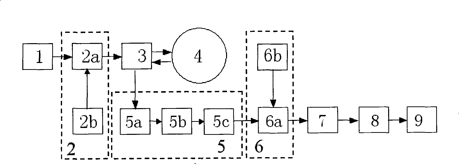
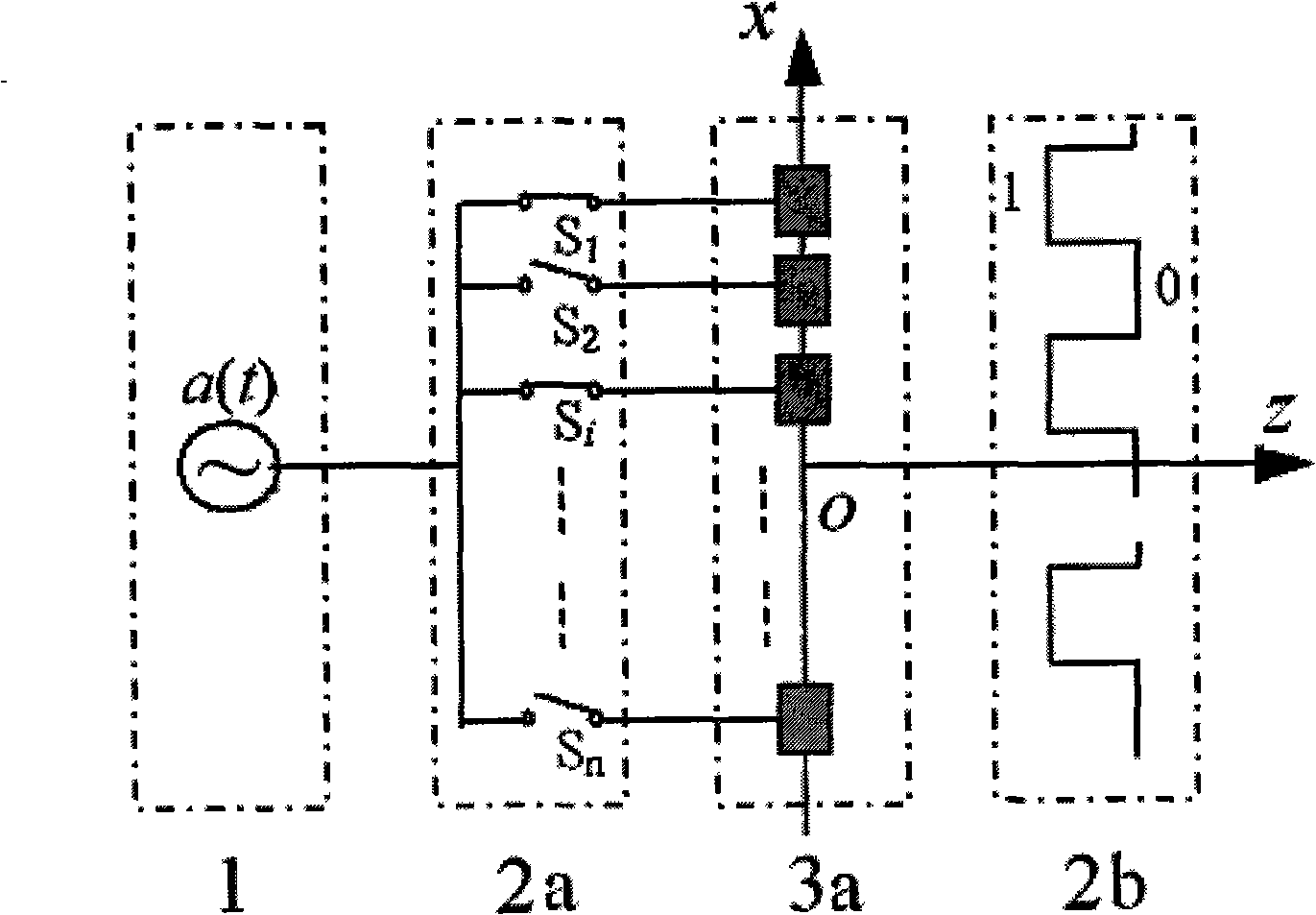
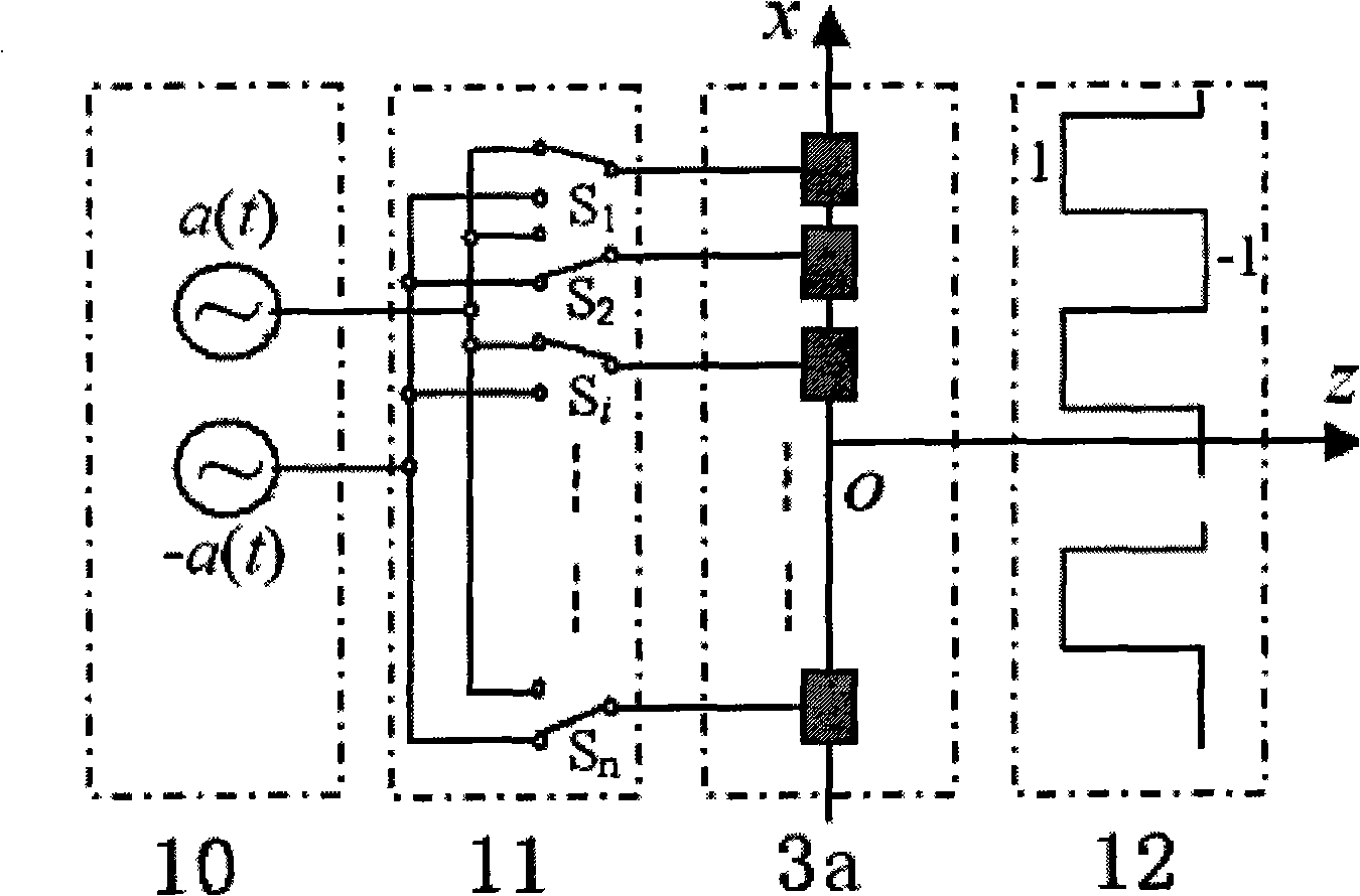
[0018] For the sake of clarity, only the transmitting circuit of the one-dimensional linear array element in the ultrasonic probe is given, and its principle can be directly extended to the transmitting circuit of the two-dimensional array element

[0019] For a one-dimensional ultrasonic linear probe, the emission parameter is k x t The expression of Array Beam is:

[0020] φ array ( x , z ) = A ( k ) e j ( k x t ...


PUM


Abstract

The invention relates to a high frame rate (HFR) ultrasonic imaging method based on a single power signal source and a switched network thereof, and the invention can realize the HFR ultrasonic transmission by using only one power signal source and a simple electronic switched network. Compared with the conventional ultrasonic imaging, the high frame rate ultrasonic imaging method uses only one channel of the power signal source and the simple electronic switched network to replace N power signal (source) amplification circuits, thus greatly simplifying the HFR system and reducing the power consumption of the circuit. The high frame rate ultrasonic imaging method approximately uses only a half of ultrasonic array elements for transmitting the signals, so the transmission energy of the device is reduced and the power supply to a future portable medical ultrasonic diagnostic imaging device by using a batter becomes possible. The high frame rate ultrasonic imaging method can be directly realized on a mature commercial machine, thus eliminating a delay circuit with expensive price. The HFR imaging algorithm is further utilized for carrying out the image reconstruction of the received signals and then the image with high quality is output.

Description

Technical field: [0001] The invention belongs to the field of medical ultrasound application, and is an ultrasound transmission system based on non-diffraction wave high frame rate (High Frame Rate, HFR) imaging, which creates favorable conditions for the realization of the HFR ultrasound imaging theory. Background technique: [0002] At present, in a high frame rate (High Frame Rate, HFR for short) imaging system, a finite diffractive wave array (Array Beam) is used as the transmitting signal for the transmitting signal. In actual implementation, a general ultrasonic probe has several transmitting array elements, and each transmitting array element needs to be driven by a power signal source. If the ultrasonic probe has N transmitting array elements, N power signal sources are required to drive each transmitting array element respectively. The relationship between these N power signal sources: the waveform is the same, but the phase and amplitude are different, so in order ...

Claims


Application Information

Patent Timeline
Patent Type & Authority Applications(China)
IPC IPC(8): A61B8/00G01N29/04
CPCA61B8/56
Inventor 彭虎李洪旺
Owner UNIV OF SCI & TECH OF CHINA
Why Eureka
Try Eureka