Liquid directly fed type writing instrument

A direct-liquid type and pen tool technology, which is applied to writing utensils, other ink pens, printing, etc., can solve the problems of inability to alternate air and ink, cheap supply, and large number of parts, so as to reduce costs, simplify structures, and shorten vertical lines. The effect of long dimensions

Active Publication Date: 2008-10-01
THE PILOT INK CO LTD
View PDF3 Cites 10 Cited by
  • Summary
  • Abstract
  • Description
  • Claims
  • Application Information

AI Technical Summary

Problems solved by technology

[0009] The structure of the brush-like pen tool of the above-mentioned Patent Document 3 is that only one ink conduit is used to connect the ink tube and the ink absorbing body, and it cannot be used quickly when the ink starts to flow out (that is, when the ink is initially supplied from the ink tube to the liquid-absorbing material). Alternate air and ink, it takes a long time to write
Moreover, the direct liquid type pen tool of the above-mentioned Patent Document 3 has a large number of parts and a complicated structure, and it is difficult to provide the user with a low cost.

Method used


Image

  • Liquid directly fed type writing instrument
  • Liquid directly fed type writing instrument
  • Liquid directly fed type writing instrument

Examples


no. 1 Embodiment

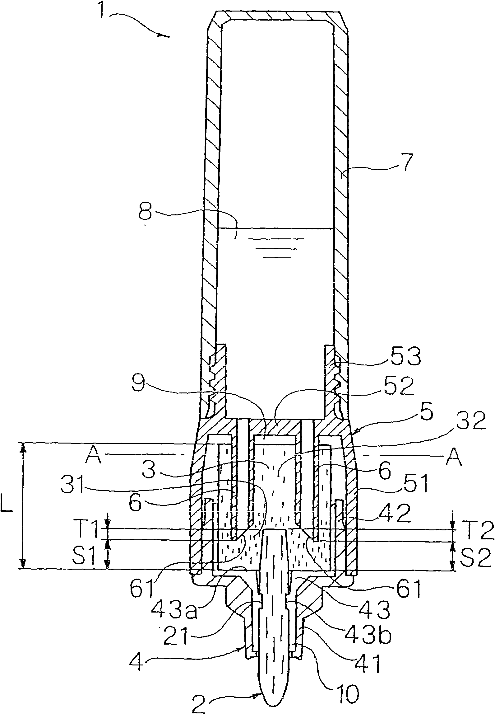
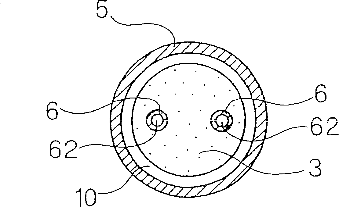
[0179] Figure 1 to Figure 2 A direct fluid writing tool 1 according to a first embodiment of the present invention is shown.

[0180] The direct-liquid pen tool 1 of this embodiment has: a pen tip 2; an ink absorbing body 3 connected to the rear end of the pen tip 2; an absorbing body housing part, which holds the above-mentioned pen tip 2 at the front end and accommodates the above-mentioned ink absorbing body 3 inside; The ink tube 7 is installed at the rear of the above-mentioned absorber housing part, and directly stores the ink 8 inside; the partition plate 52 divides the above-mentioned absorber housing part and the above-mentioned ink tube 7; and a plurality of (specifically, two) communication tubes 6, It protrudes forward from the front surface of the above-mentioned partition plate 52 , pierces through and is connected to the inside of the ink absorber 3 . The absorber housing portion has a tip member 4 holding the pen tip 2 and an intermediate member 5 connecting ...

no. 2 Embodiment

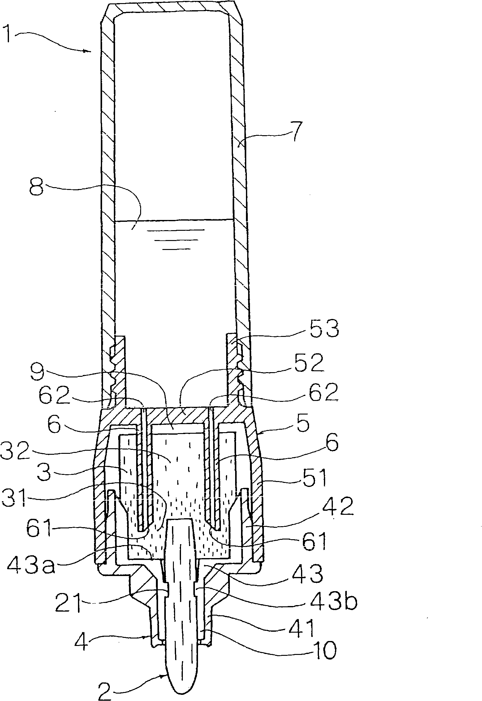
[0203] image 3 Shows the second embodiment of the present invention.

[0204] This embodiment is a modified example of the first embodiment. The difference from the first embodiment is that the high-density portion 31 is formed on the front portion of the ink absorber 3 by pressing and compressing the front outer peripheral surface of the ink absorber 3 inward in the radial direction.

[0205] The diameter of the inscribed circle of the plurality of ribs 43 formed on the inner surface of the large-diameter portion 42 of the front end member 4 is set to be slightly larger than the outer diameter of the front portion of the ink absorber 3 . The above-mentioned ink absorber 3 has a uniform density distribution in the front-rear direction before it is press-fitted into the tip member 4 . In addition, when the front portion of the ink absorber 3 is pressed into the large-diameter portion 42 of the front end member 4, the outer peripheral surface of the front portion of the ink a...

no. 3 Embodiment

[0207] Figure 4 Shows the third embodiment of the present invention.

[0208] This embodiment is a modified example of the first embodiment, and differs from the first embodiment in that a high-density portion 31 is formed at the front of the ink absorber 3 by pressing and compressing the front end of the ink absorber 3 backward.

[0209] On the restricting wall portion 43a of the plurality of ribs 43 formed on the inner surface of the front end member 4, a piercing portion 43c that protrudes large backward is integrally formed. Before the ink absorber 3 is press-fitted into the front end member 4, it has a uniform density distribution in the front-rear direction. And, if the front part of the above-mentioned ink absorbing body 3 is inserted into the large-diameter portion 42 of the above-mentioned front end member 4, the above-mentioned piercing portion 43c is deeply inserted into the front end surface of the above-mentioned ink absorbing body 3, and the front end of the in...


PUM


Abstract

A direct-fluid-supply writing implement has a pentip, an ink occluding element connected to a rear end of the pentip, the ink occluding element including a high-density portion, and a low density portion continuously connected to a rear of the high density portion, an ink tank disposed at rear of the ink occluding element and adapted to directly store ink and pluralities of communicating tubes connecting the ink tank with the ink occluding element, the respective communicating tubes including an opened front end, wherein the front end of the communicating tube and the rear end of the pentip connect with the high-density portion.

Description

[0001] This application is a divisional application of the application whose filing date is September 14, 2005, the application number is 200510099289.8, and the invention title is "Straight Liquid Pen Tool". technical field [0002] The present invention relates to a direct-liquid type writing tool in which ink is directly stored in an ink tube, and an ink absorbing body is inserted between the above-mentioned ink tube and the nib. Also, in the present invention, "front" means the nib side; "rear" means the ink tube side. Background technique [0003] In the past, in this type of direct fluid writing tool, for example, disclosed in Patent Document 1 "a kind of writing tool, it is characterized in that: have: receiving body, have connecting pipe and through-hole and fill in the upper opening of ink container The absorbent material; the ink container, inserted into the above-mentioned container at the upper opening; the nib, inserted into the above-mentioned absorbent materia...

Claims


Application Information

Patent Timeline
Patent Type & Authority Applications(China)
IPC IPC(8): B43K8/04B43K8/06
Inventor 栗田哲宏稻叶孝男
Owner THE PILOT INK CO LTD
Why Eureka
Try Eureka