Dynamic carding method and device thereof

A carding and moving technology, used in deburring devices, textiles and papermaking, fiber processing, etc., and can solve problems such as inability to achieve

Inactive Publication Date: 2008-10-01
HERGETH H
View PDF10 Cites 8 Cited by
  • Summary
  • Abstract
  • Description
  • Claims
  • Application Information

AI Technical Summary

Problems solved by technology

This cannot be achieved in practice

Method used


Image

  • Dynamic carding method and device thereof
  • Dynamic carding method and device thereof
  • Dynamic carding method and device thereof

Examples


Embodiment Construction

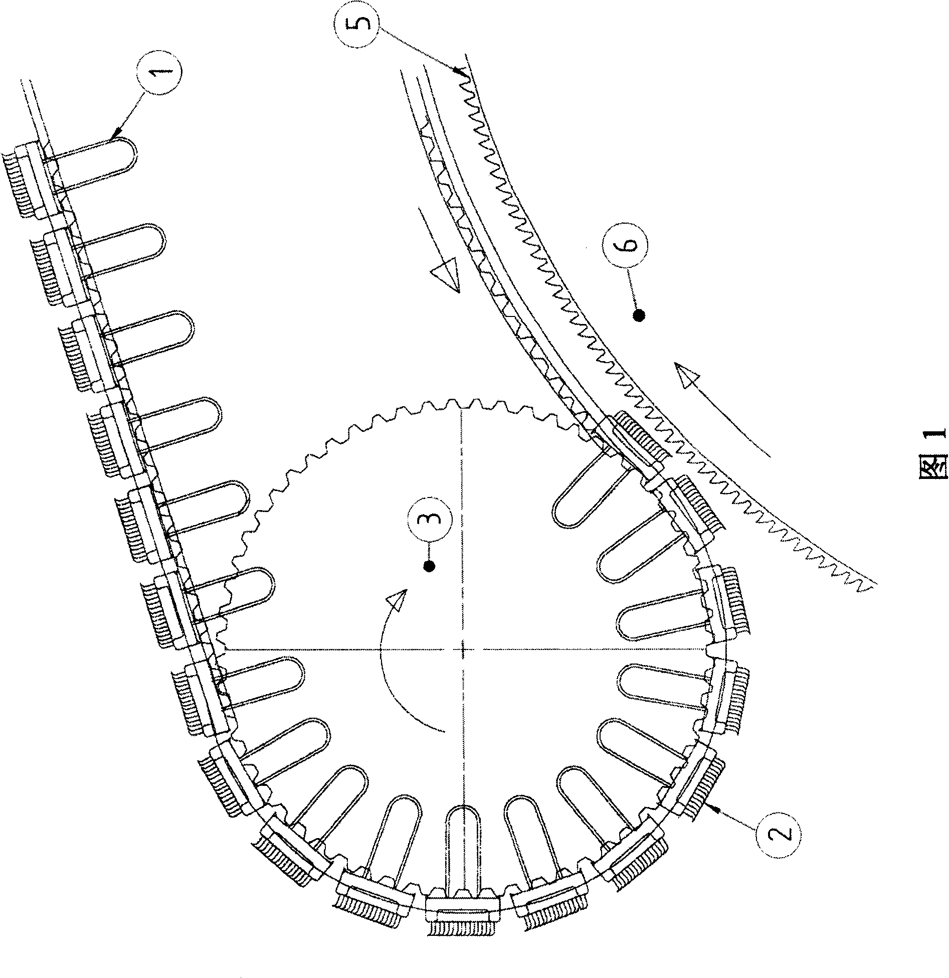
[0043] FIG. 1 shows the entry and exit of a flat 1 with movable clothing 2 . The cover plate is taken off or put on from the flexible arcuate plate (not shown here) by a guide roller 3 . The movable clothing 2 is located together with the stationary clothing 5 of the cylinder 6 after an entry zone or exit zone 4 during the opening process.

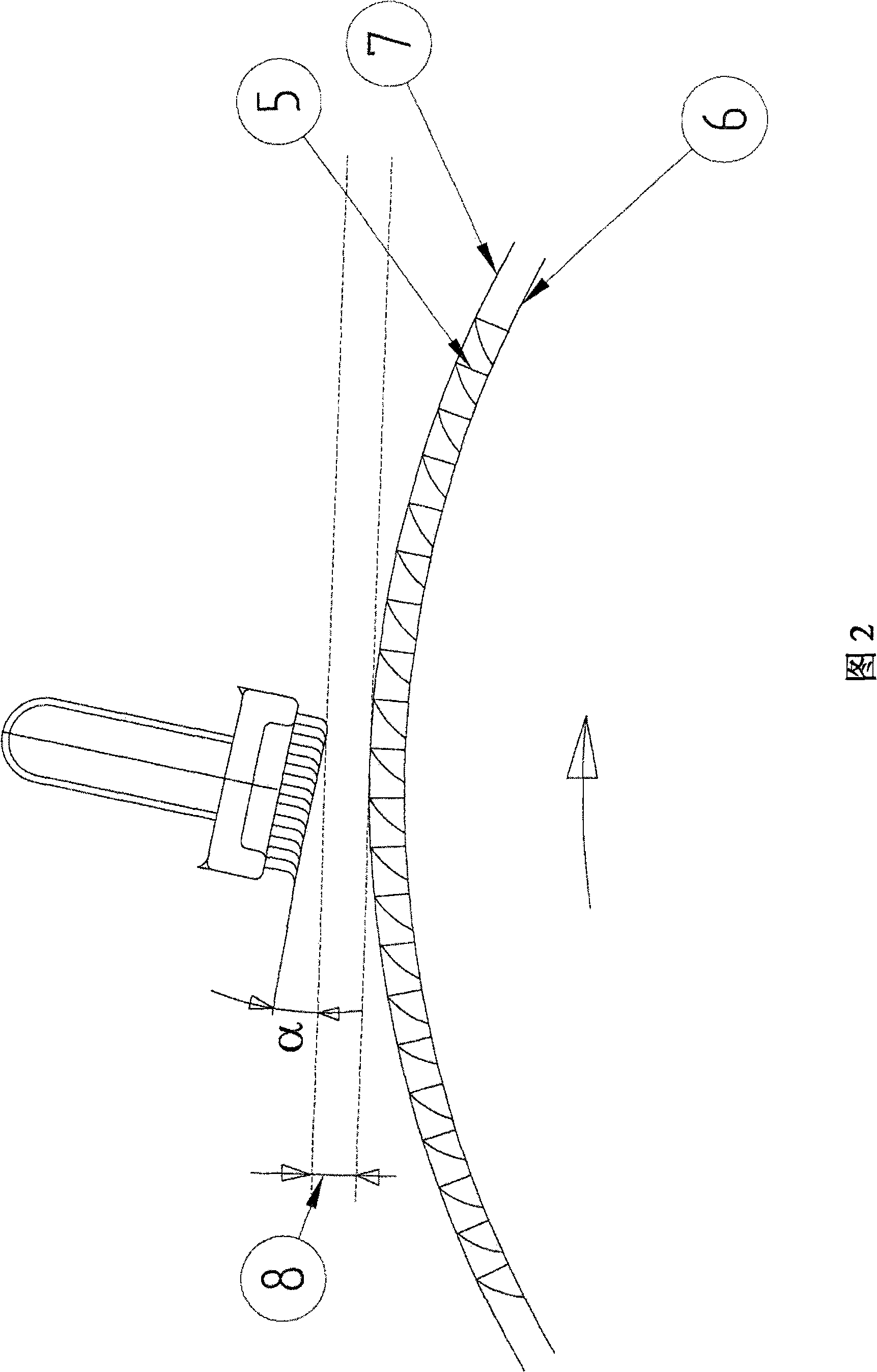
[0044] Figure 2 shows the inclined position of the movable card clothing. Line 7 shows the working outer circle (Schlagkreis) formed by the clothing 5 of the cylinder 6 . The distance 8 shows the narrowest distance between the movable card clothing of the flat plate and the working outer circle of the cylinder card clothing.

[0045] The angle α shows the inclination angle between the imaginary tangent line of the working outer circle of the cylinder card clothing at the narrowest distance and the top plane of the movable card clothing of the cover plate. Angle α can also be the angle between another point on the card clothing, such as ...


PUM


Abstract

The invention relates to a dynamic carding method for carding fibers with a carding machine having card-flat rods fitted with card clothing moves the card-flat rods in a carding zone in relation to the peripheral surface of a swift along a scheduled path and a device thereof; wherein, at least one card clothing moves instantaneously in a direction deviated from the scheduled path at least one time passing through the carding zone, and then returns to the scheduled path. The feature of the device for carding fibers according to the carding method of the invention is that the invention comprises a device that makes at least one card clothing deviate instantaneously from the scheduled path, and then return to the scheduled path.

Description

technical field [0001] The invention relates to a carding machine with a cover plate and a dynamic carding method thereof. Background technique [0002] Since the end of the Second World War, the production process for obtaining products by means of cards with flats (Deckelkarde) has increased from 5 kg / h to about 60 kg / h at combed quality and about 80 kg / h at open quality. And also in the case of the worst quality, a fiber throughput of more than 200 kg becomes possible. This development in production has been achieved through the use of all-steel card clothings, improved card clothing geometries, carding components and improvements in feeding sliver and lapping. However, there has been no further production progress in recent years. This can be traced back to the fact that the heart of the card differs from the carding unit, i.e. the opening process itself cannot be improved by rotating the flats. In Melliand Textile Report 11-12 / 2006, p. 787, "Short time storage and ca...

Claims


Application Information

Patent Timeline
Patent Type & Authority Applications(China)
IPC IPC(8): D01G15/02D01G15/28
CPCD01G15/24D01G15/08
Inventor 安克·维克博恩
Owner HERGETH H
Why Eureka
Try Eureka