Driving support method and driving support apparatus

A driving assistance and driver technology, applied in transportation and packaging, TV, color TV parts, etc., can solve the problems of uncoordinated drivers and large differences, and achieve the effect of reducing the amount of processing

Inactive Publication Date: 2008-10-01
AISIN AW CO LTD
View PDF1 Cites 58 Cited by
  • Summary
  • Abstract
  • Description
  • Claims
  • Application Information

AI Technical Summary

Problems solved by technology

However, when looking at the rear or the side rear through the interior rearview mirror, the range and direction of sight that the driver can observe are different from the observation range and direction of sight when the driver directly looks at the rear or the side rear. method, the difference between the image projected on the pillar and the actual scene is very large, and the driver sometimes feels uncoordinated

Method used


Image

  • Driving support method and driving support apparatus
  • Driving support method and driving support apparatus
  • Driving support method and driving support apparatus

Examples


Embodiment Construction

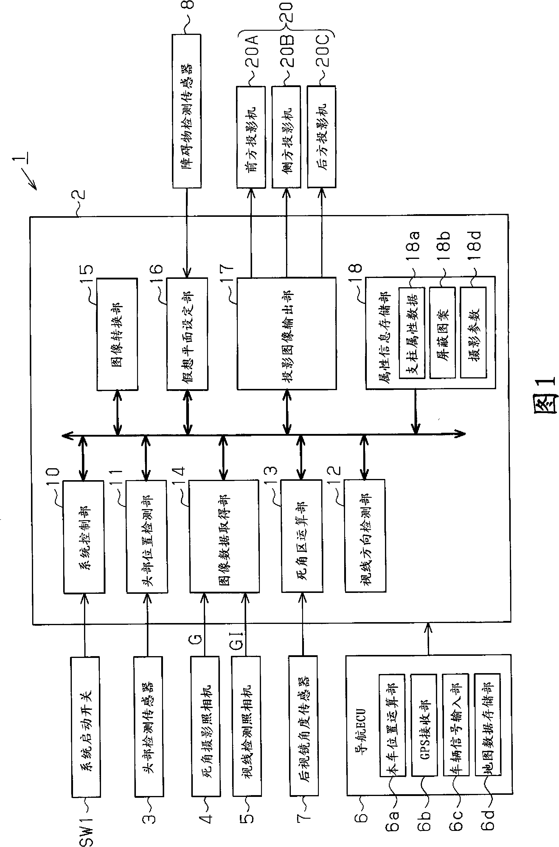
[0030] Below, combined with Figure 1~ Figure 12 , an embodiment of the present invention will be described, and FIG. 1 illustrates the figure 2 ) is a block diagram showing the configuration of the driving assistance system 1 .

[0031] The driving assistance system 1 is mounted on the host vehicle C1, and as shown in FIG. A mirror angle sensor 7 , an obstacle detection sensor 8 , a navigation ECU (hereinafter, navigation ECU 6 ), and a projector 20 as a display device and a projection device.

[0032] The driving assistance unit 2 has a system control unit 10 as a vehicle status determination unit, a head position detection unit 11 as a driver position detection unit, a line-of-sight direction detection unit 12, a rearview mirror position detection unit, and a dead-spot area calculation unit. A dead-spot calculation unit 13 and an image data acquisition unit 14 of the viewing range calculation unit. In addition, it also has an image conversion unit 15 as an image synthesi...


PUM


Abstract

A driving support method for capturing an area which is hidden as a blind spot arising because of a presence of a pillar of a vehicle by using a blind spot camera which is mounted in the vehicle and for displaying an image corresponding to the blind spot area on a medial side of the pillar detects a head position of a driver, obtains an angle of a rear-view mirror which is mounted in the vehicle, calculates the area which is hidden as a blind spot arising because of the presence of the pillar in the rear-view mirror on the basis of the driver's head position and the angle of the rear-view mirror, provided that the driver looks at an area surrounding the vehicle through the rear-view mirror, and projects an area corresponding to the blind spot on the pillar from image data which is provided by the blind spot camera.

Description

technical field [0001] The present invention relates to a driving assistance method and a driving assistance device. Background technique [0002] Conventionally, as a device for assisting safe driving, an in-vehicle system has been developed in which an in-vehicle camera captures an area that becomes a driver's blind spot and displays it on a monitor or the like. As one of such systems, a system has been proposed that uses an on-vehicle camera to photograph a blind spot area formed by a pillar of a vehicle, and displays the photographed image inside the pillar (for example, refer to Patent Document 1). Pillars are the left and right pillars that support the windows and the roof. Although they block part of the driver's field of vision, they must have a specified thickness for safety. In addition, since the driver's line of sight does not coincide with the camera's shooting direction, this device performs coordinate conversion on the captured image of the camera to match th...

Claims


Application Information

Patent Timeline
Patent Type & Authority Applications(China)
IPC IPC(8): H04N7/18H04N5/74B60R11/00
CPCB60R2300/202
Inventor 冈部英文高木实
Owner AISIN AW CO LTD
Why Eureka
Try Eureka