Trickle bed reactor

A technology of reactor and trickle bed, applied in the field of trickle bed reactor

Active Publication Date: 2011-02-09
SHANGHAI RES INST OF PETROCHEMICAL TECH SINOPEC
View PDF2 Cites 6 Cited by
  • Summary
  • Abstract
  • Description
  • Claims
  • Application Information

AI Technical Summary

Problems solved by technology

[0007] The technical problem to be solved by the present invention is that the gas-liquid distribution in the trickle bed reactor in the prior art is not uniform, resulting in poor dripping effect in the reactor and catalytic To solve the problem of low reaction efficiency, a new trickle bed reactor is provided

Method used


Image

  • Trickle bed reactor
  • Trickle bed reactor
  • Trickle bed reactor

Examples


Embodiment 1

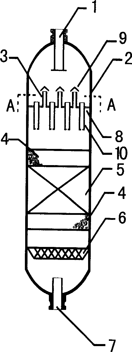
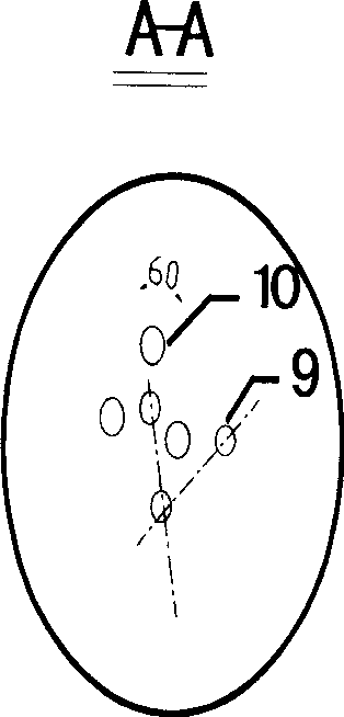
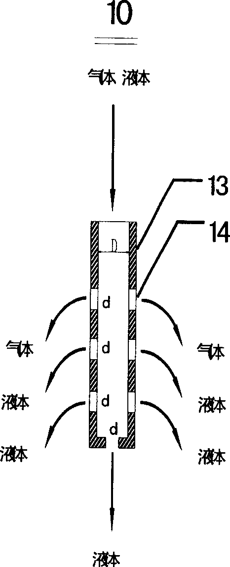
[0023] As shown in Figure 1, the initial pyrolysis gasoline C 5 ~C 9 Fractions (oils) with a diene value greater than 25 g I 2 / 100 grams of Oil, hydrogen enters the trickle bed reactor with a hydrogen-oil ratio equal to 100, the catalyst adopts a general-purpose palladium series hydrogenation catalyst, adopts the trickle bed reactor of the present invention, and the gas-liquid distributor 3 is located below the feed port 1 800 millimeters, be positioned at the top 1000 millimeters of upper ceramic ball bed layer 4; The upper end of short pipe 13 stretches out 50 millimeters above distribution plate 8, and the lower end stretches out 500 millimeters below distribution plate 8, and the diameter d of aperture 14 and liquid channel pipe 10 The ratio of the inner diameter D is 0.015:1.0, the area S of all small holes 14 1 and the area S of the inner cross-section of the liquid channel tube 10 2 The ratio of the ratio is 1.01:1.0; the opening ratio of the gas passage pipe 9 on t...

Embodiment 2

[0025] As shown in Figure 1, the initial pyrolysis gasoline C 5 ~C 9 Fractions (oils) with a diene value greater than 25 g I 2 / 100 grams of Oil, hydrogen enters the trickle bed reactor with a hydrogen-oil ratio equal to 100, the catalyst adopts a general-purpose palladium series hydrogenation catalyst, adopts the trickle bed reactor of the present invention, and the gas-liquid distributor 3 is located below the feed port 1 500 millimeters, be positioned at the top 800 millimeters of upper ceramic ball bed layer 4; The upper end of short pipe 13 stretches out 90 millimeters above distribution plate 8, and the lower end stretches out 800 millimeters below distribution plate 8, and the diameter d of aperture 14 is the same as liquid channel pipe 10 The ratio of the inner diameter D is 0.011:1.0, the area S of all small holes 14 1 and the area S of the inner cross-section of the liquid channel tube 10 2 The ratio of the ratio is 0.95:1.0; the opening ratio of the gas passage tu...

Embodiment 3

[0027] As shown in Figure 1, the initial pyrolysis gasoline C 5 ~C 9 Fractions (oils) with a diene value greater than 25 g I 2 / 100 grams of Oil, hydrogen enters the trickle bed reactor with a hydrogen-oil ratio equal to 100, the catalyst adopts a general-purpose palladium series hydrogenation catalyst, adopts the trickle bed reactor of the present invention, and the gas-liquid distributor 3 is located below the feed port 1 300 millimeters, be positioned at the top 600 millimeters of upper ceramic ball bed layer 4; The upper end of short pipe 13 stretches out 60 millimeters above distribution plate 8, and the lower end stretches out 650 millimeters below distribution plate 8, and the diameter d of aperture 14 is the same as liquid channel pipe 10 The ratio of the inner diameter D is 0.15:1.0, the area S of all small holes 14 1 and the area S of the inner cross-section of the liquid channel tube 10 2 The ratio is 1.1:1.0; the opening ratio of the gas passage tube 9 on the di...


PUM


Abstract

The invention relates to a trickle-bed reactor, which mainly aims at solving the problem that the uneven liquid-gas distribution of the trickle-bed reactor in the prior art results in the bad trickling effect of the reactor and low efficiency of the catalytic reaction. The trickle-bed reactor adopts the technical scheme that the trickle-bed reactor comprises an inlet orifice, a reactor shell, a liquid-gas distributor, a porcelain ball bed layer, a catalyst bed layer and an orifice ring, wherein the liquid-gas distributor is provided with a gas passage pipe and a liquid passage pipe on a distributing plate; the gas passage pipe is composed of a cone roof and a straight nozzle stub; the liquid passage pipe is a vertical nozzle stub with the upper end extending 10 to 100mm out of the upper part of the distributing plate and the lower end extending 200 to 1000mm out of the lower part of the distributing plate; a plurality of pinholes are evenly opened on the cross section at different positions along the axial direction to form the liquid-gas distributor. The technical scheme better solves the problem, greatly improves the reaction efficiency of the trickle-bed reactor and can be applied to various gas liquid and solids three-phase reactors.

Description

technical field [0001] The invention relates to a trickle bed reactor. Background technique [0002] Trickle bed reactor is one of the main types of reactors, because it not only has the advantages of simple structure and low equipment investment, but also has the characteristics of convenient operation and large operation flexibility. Therefore, trickle bed reactors are widely used in oil refining and chemical industry. Especially in the fields of hydrocracking of oil products and hydrofining of hydrocarbons, trickle bed is one of the most basic reactors. One of the characteristics of the trickle bed reactor is that the gas and liquid in the reactor flow through the catalyst bed in parallel, wherein the liquid flows through the catalyst bed in a trickle flow, while the gas passes through in a continuous flow. Therefore, whether the liquid can form a trickle flow in the reactor and whether the gas distribution is uniform are the main factors affecting the design of the tri...

Claims


Application Information

Patent Timeline
Patent Type & Authority Patents(China)
IPC IPC(8): B01J8/04
Inventor 甘永胜李斌
Owner SHANGHAI RES INST OF PETROCHEMICAL TECH SINOPEC
Why Eureka
Try Eureka