Engine performance measuring system

A test system and engine technology, applied in the direction of engine testing, machine/structural component testing, measuring devices, etc., can solve problems such as damage to the dynamometer, the influence of the balance of engine motion, and the inability to conduct experiments, and achieve vibration reduction. , to prevent damage, the effect of stable speed

Inactive Publication Date: 2008-10-08
力帆科技(集团)股份有限公司
View PDF0 Cites 3 Cited by
  • Summary
  • Abstract
  • Description
  • Claims
  • Application Information

AI Technical Summary

Problems solved by technology

[0003] 1. For an engine with a relatively small displacement, although the engine performance test can be completed, after the engine driving wheel fixed plate combination and the driving wheel sliding plate combination are removed, the engine’s motion balance will be affected, which cannot truly reflect the engine’s operating conditions. Therefore, the data obtained from the test cannot reflect the actual performance of the engine
[0004] 2. For an engine with a relatively large displacement, the combination of the fixed plate of the driving wheel and the sliding plate of the driving wheel plays the role of balancing the moment

Method used


Image

  • Engine performance measuring system
  • Engine performance measuring system
  • Engine performance measuring system

Examples


Embodiment Construction

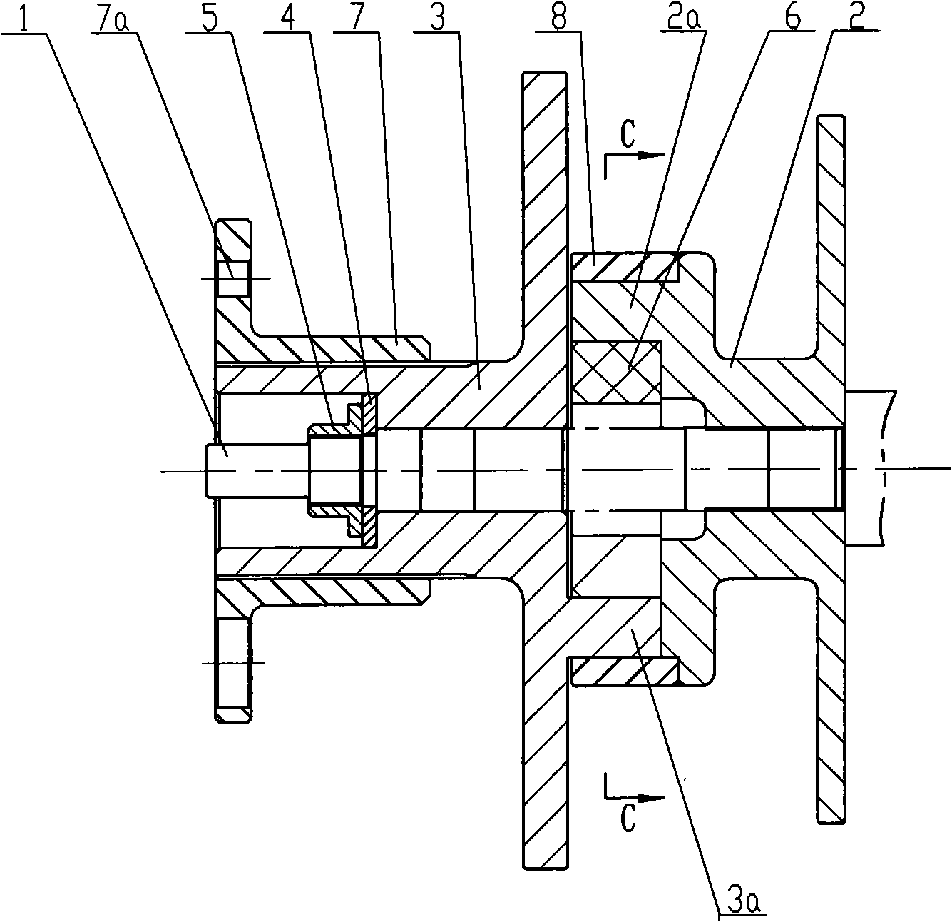
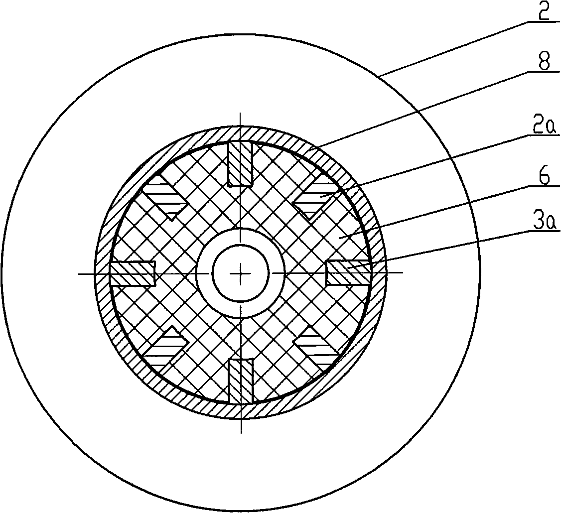
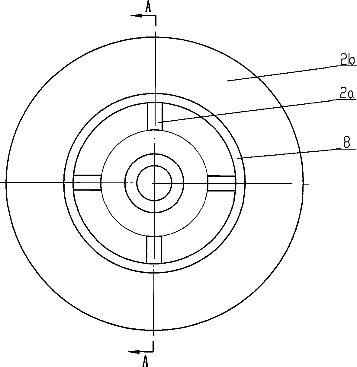
[0025] Below in conjunction with accompanying drawing and embodiment the present invention will be further described:

[0026] Such as figure 1 , figure 2 , image 3 with Figure 4 As shown, the present invention is made of parts such as automatic clutch driving wheel shaft 1, first flywheel 2, second flywheel 3, washer 4, nut 5, damping sleeve 6 and connecting sleeve 7, wherein automatic clutch driving wheel shaft 1 is prior art , its structure will not be repeated here. The first flywheel 2 is formed by machining, the center hole of the first flywheel 2 is two-stage stepped, and an internal spline is processed in the small diameter section of the center hole. One end of the first flywheel 2 is processed with 2 to 4 rectangular (can be other shapes) active teeth 2a, each active tooth 2a is evenly distributed on the circumference, and the root of each active tooth 2a is connected with the disk surface of the small disc 2c, The other end of the first flywheel 2 is process...


PUM


Abstract

The utility model relates to an engine performance test system, which is provided with a first flywheel and a second flywheel arranged on the axis of the driving wheel of an automatic clutch side by side. The first flywheel is connected with the spline of the axis of the driving wheel of the automatic clutch. The second flywheel is looped on the axis of the driving wheel of the automatic clutch. The abutting end of the first wheel and the second wheel is provided with teeth. The driving teeth of the first wheel and the driven teeth of the second wheel are respectively inserted in corresponding key walls of a shock-absorbing sleeve. The driving teeth and the driven teeth are arranged at regular intervals. The second flywheel is covered with a connection sheath which is connected with the spline of the second flywheel. The utility model can accurately reflect the operational state of engines, accurately detect the performance parameter of engines, effectively prevent the bent axle of engines or the axis of the driving wheel of the clutch and a dynamometer machine from being damaged and ensure the experiment going with a swing when the engine performance is tested by simulating the structure of the fixed disk combination and the sliding disk combination of the driving wheel of engines. The utility model is suitable for stepless speed change engines of big and small delivery capacity.

Description

technical field [0001] The invention belongs to the technical field of engine performance testing, in particular to an engine performance testing system. Background technique [0002] With the superiority of continuously variable transmission and the improvement of manufacturing level, many motorcycles now use continuously variable transmission engines, especially more common on special motorcycles (ATV, kart, farmer's car, etc.). The internal structure of the continuously variable transmission engine is shown in Figure 10, which generally includes a crankshaft 9, a piston crank linkage mechanism 10, an automatic clutch 11, a drive wheel fixed disc combination 12, a driving wheel sliding disc combination 13, a driven wheel combination 14, and a main shaft 15 And speed change mechanism 16, wherein the driving wheel shaft 1 of automatic clutch 11 is connected with crankshaft 9 by spline, driving wheel fixed disc combination 12 and driving wheel sliding disc combination 13 are ...

Claims


Application Information

Patent Timeline
IPC IPC(8): G01M15/00
Inventor 杨世容上官维涛刘克君马丽江
Owner 力帆科技(集团)股份有限公司
Why Eureka
Try Eureka