Fault injection system and method for verifying anti-single particle effect capability

An anti-single event effect and fault injection technology, applied in special data processing applications, instruments, electrical digital data processing, etc., can solve problems such as high requirements for software and hardware equipment, unfavorable automation, non-uniform random selection, etc., to improve computing Speed, increased versatility, and ease of operation

Inactive Publication Date: 2008-10-08
BEIJING MXTRONICS CORP +1
View PDF2 Cites 45 Cited by
  • Summary
  • Abstract
  • Description
  • Claims
  • Application Information

AI Technical Summary

Problems solved by technology

[0011] The main disadvantage of the above method to verify the single event effect is that the pulse width of the injected fault effect is equal to the system clock cycle, that is, only the single event upset (SEU) effect is simulated, and the single event transient (SET) effect in the combinational logic circuit is simulated. The pulse width is much smaller than the system clock cycle of the semiconductor device circuit, that is, the clock cycle that needs to inject faults is much smaller than the clock cycle of the circuit, and these fault injection methods do not simulate this process
In addition, there is also a problem that the selection of circuit nodes is not uniformly selected at random. The probability of single event effects occurring on each node (logic gate) of the circuit is approximately equal, and the above method is only used in some specific circuit signals, circuit Faults are injected on nodes, and single event effects are not simulated on all circuit nodes (logic gates), that is, there is a problem of fault injection coverage
[0012] In summary, using the current fault injection methods to verify the anti-single event effect of large-scale target circuits requires high hardware and software equipment, making it difficult to implement fault injection for verifying anti-single event effects. In addition, manual intervention is required. It is not conducive to automation. In terms of simulating the type of single event effect, the pulse width of single event effect, the circuit node where the single event effect occurs and the coverage rate, it is difficult to be close to the physical process of the single event effect in the real space, and it is easy to miss , cannot meet the current demand for large-scale circuit anti-single event effect verification

Method used


Image

  • Fault injection system and method for verifying anti-single particle effect capability
  • Fault injection system and method for verifying anti-single particle effect capability
  • Fault injection system and method for verifying anti-single particle effect capability

Examples


Embodiment Construction

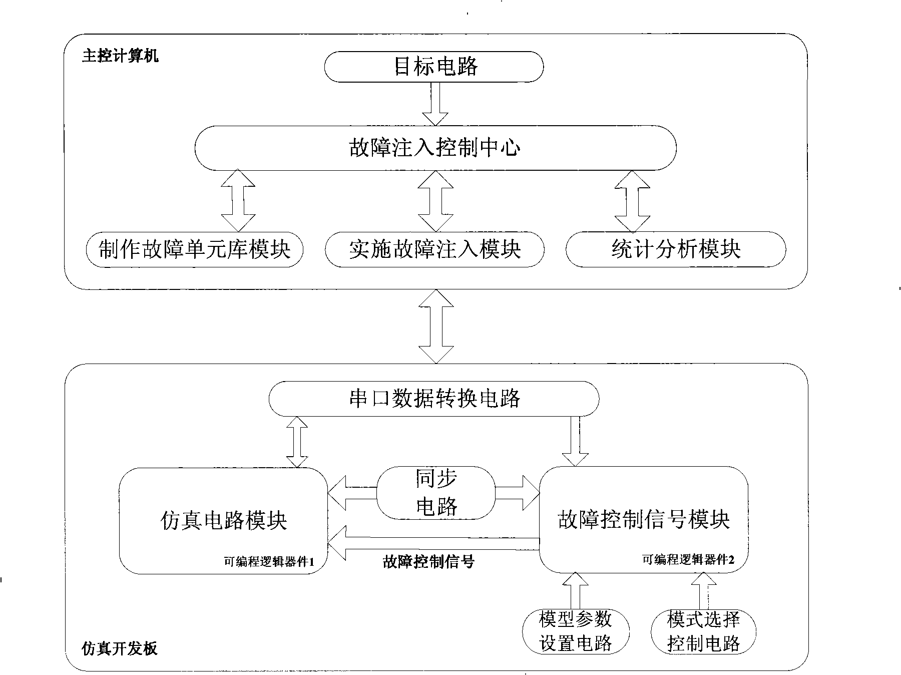
[0062] Such as figure 1 A structural schematic diagram of the fault injection system for verifying the single event effect of the present invention is illustrated. The system of the present invention includes making a fault unit library module, implementing a fault injection module, a statistical analysis module, a synchronous circuit, a simulation circuit module and a fault control signal module; the main control computer contains a fault injection control center, making a fault cell library module, and implementing fault injection Module, statistical analysis module, the main control computer is connected with the simulation circuit module and the fault control signal module through the serial port data conversion circuit, the serial port data conversion circuit is RS232 serial port circuit, USB transmission circuit, network cable transmission circuit, etc., the model parameter setting circuit is multi-bit The dial switch circuit is connected to the input terminal of the fau...


PUM


Abstract

The invention relates to a fault injection system for verifying anti-single-particle-effect ability. A fault unit library fabrication module modifies a process unit library of an objective circuit to a fault unit library of the objective circuit; a fault injection implementation module modifies the gate level HDL codes of the objective circuit, generates a non-fault circuit and a fault circuit, maps the modified codes to the fault unit library, counts the number of the fault terminals of the codes and sends to a fault control signal module; a synchronous circuit realizes clock synchronization of a simulation circuit module and a fault control signal module; the fault control signal module generates a fault control signal and sends to the fault circuit of the simulation circuit module; the simulation circuit module loads the non-fault circuit and the fault circuit, provides input signals to the two circuits, provides the control signal to the non-fault circuit, compares the outputs of the two circuits and sends the comparison result and the fault control signal to a statistical analysis module to record, the statistical analysis module calculates the error rate and sensitivity of each node.

Description

technical field [0001] The invention relates to the technical field of verification of the ability of semiconductor devices to resist space single event effects. Background technique [0002] When a digital circuit is applied in a space environment, space high-energy particles will penetrate the interior of the semiconductor device and generate ionization on the path, and the circuit nodes will absorb the electrons and holes generated by the ionization, resulting in circuit errors. This effect is called single event effect . There are mainly radiation experiment methods and simulation methods for simulating single event effects on the ground. The radiation experiment method is expensive and the cycle is long, and the simulation method is low-cost and easy to implement. It has become an urgent research method for verifying the resistance of circuits against single events. [0003] At present, the simulation methods for verifying the resistance of the target circuit to space ...

Claims


Application Information

Patent Timeline
Patent Type & Authority Applications(China)
IPC IPC(8): G06F17/50
Inventor 郑宏超范隆刘立全初飞江军王振中
Owner BEIJING MXTRONICS CORP
Why Eureka
Try Eureka