
Flexible circuit board

A flexible circuit board technology, applied in the direction of circuits, printed circuit parts, electrical components, etc., can solve the problems of punching offset, material breaking, and insufficient tensile strength of flexible circuit boards, and achieve good resistance The effect of tensile strength and optimum process cleanliness

Inactive Publication Date: 2008-10-08
AU OPTRONICS CORP
View PDF0 Cites 3 Cited by
  • Summary
  • Abstract
  • Description
  • Claims
  • Application Information

AI Technical Summary

Problems solved by technology

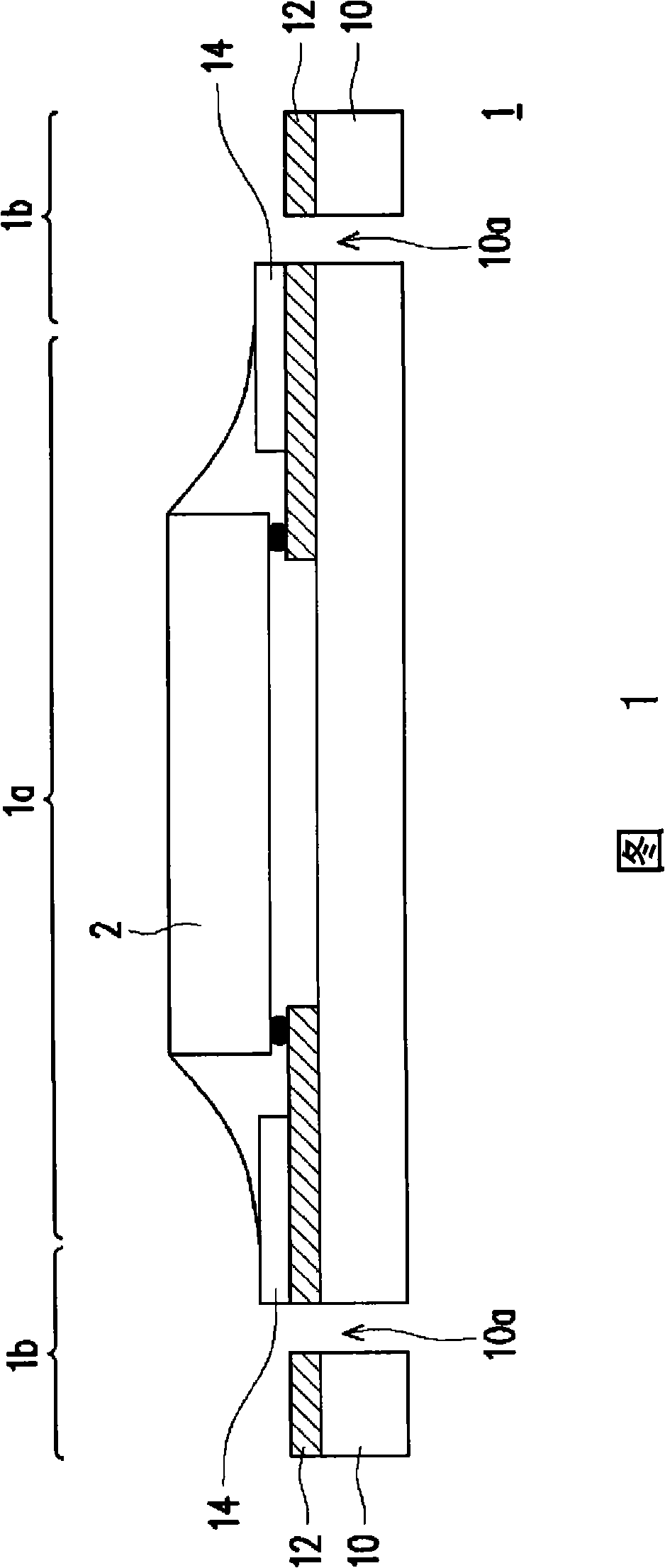
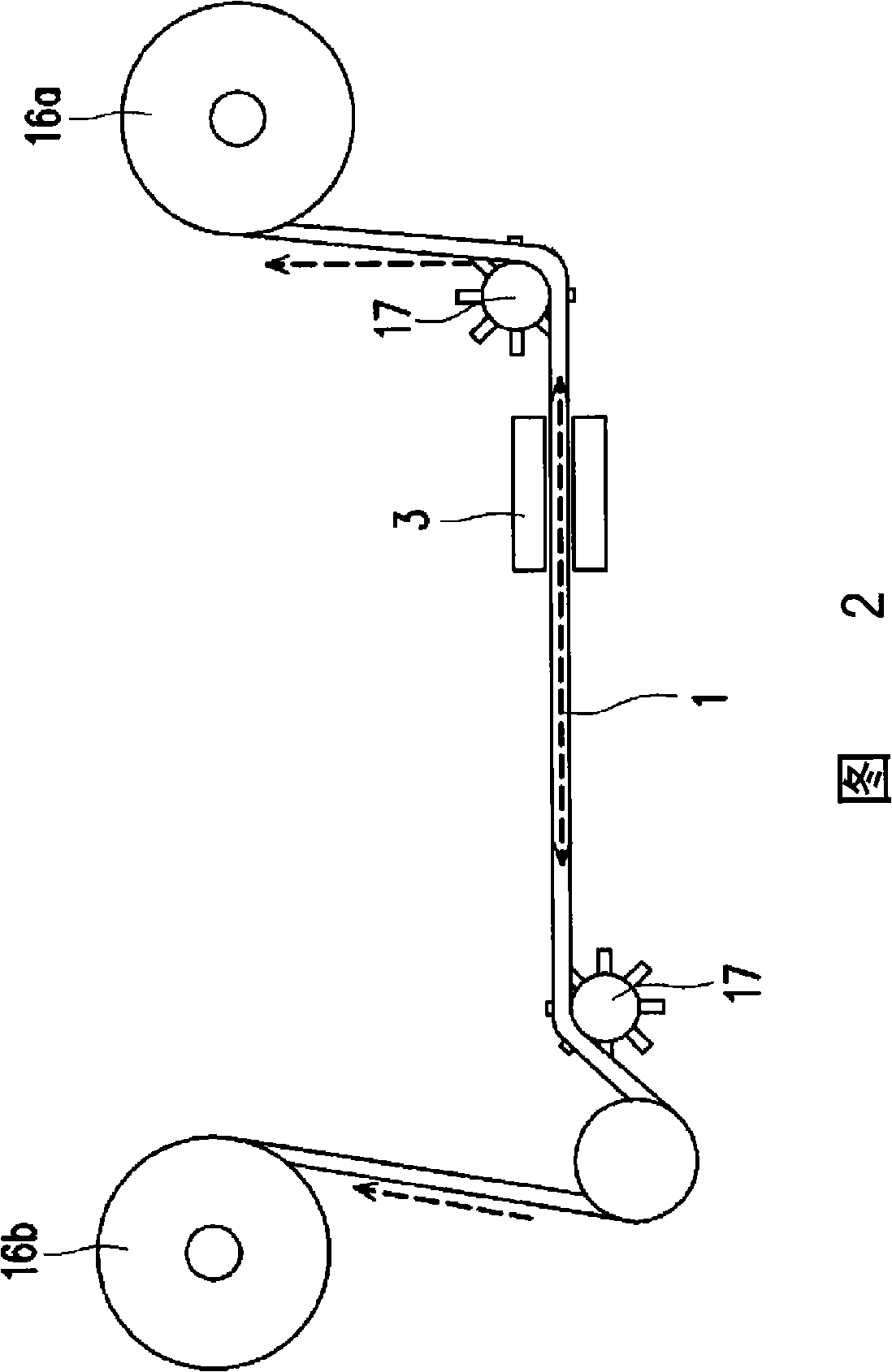
However, since the patterned metal layer 12 around the transmission hole 10a is exposed, when the gear 17 and the transmission hole 10a interfere with each other, it is easy to wear the transmission hole 10a due to friction and generate metal dust, thereby affecting the cleanliness of the process.
In addition, during the transmission process, the tensile strength of the transmission hole 10a of the flexible circuit board 1 may also be insufficient, which may easily cause material breakage or punching deviation.

Method used


Image

  • Flexible circuit board
  • Flexible circuit board
  • Flexible circuit board

Examples


Embodiment Construction

[0021] The flexible circuit board using the film-on-chip package will be described below as an embodiment. However, as mentioned above, in addition to film-on-chip packaging, tape-and-reel automatic bonding also includes tape-on-reel packaging. Therefore, the technical contents disclosed in the following embodiments are not limited to the chip-on-film packaging, but can also be applied to tape-on-reel packaging or other possible occasions.

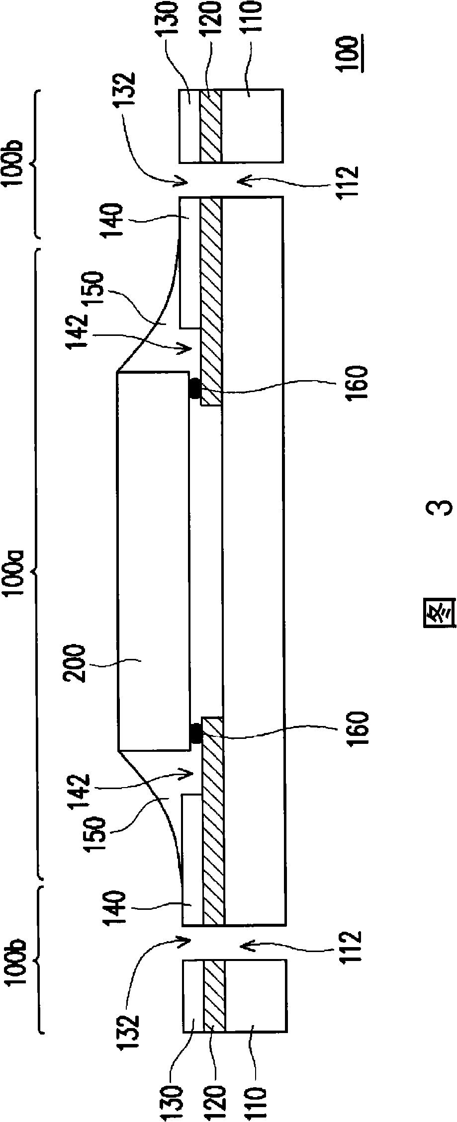
[0022] 3 is a schematic cross-sectional view of a chip disposed on a flexible circuit board according to an embodiment of the present invention, Figure 4 It is a top view of the flexible circuit board shown in FIG. 3 . It must be explained here that in order to clearly show the structure of the surface of the flexible circuit board, Figure 4 The chip and other possible components in FIG. 3 are omitted.

[0023] Please refer to Figure 3 together with Figure 4 , in this embodiment, the flexible circuit board 100 has a packaging area 100a...


PUM


Abstract

A flexible circuit board has a encapsulation region and a transmission region arranged at two opposite sides of the encapsulation region. The flexible circuit board includes a flexible base material, a patterned metal layer and a dielectric layer. The flexible base material has a plurality of holes which arranged in the transmission region. The patterned metal layer is equipped on the flexible base material, at least covers the flexible base material in the transmission region and exposes the transmission holes. The dielectric layer covers the patterned metal layer in the transmission layer and exposes the transmission holes.

Description

【Technical field】 [0001] The present invention relates to a printed circuit board (Printed Circuit Board, PCB), and in particular to a flexible printed circuit board (Flexible Printed Circuitry, FPC). 【Background technique】 [0002] There are many different types of printed circuit boards, some are rigid and others are flexible or soft. Flexible circuit board is a kind of circuit board supported by soft dielectric materials, which can be used as flexible cables or applied in continuous dynamic bending products, and is currently used in the packaging of LCD driver ICs It is especially widely used in mobile electronic products, such as mobile phones, notebook computers and digital cameras. [0003] Generally speaking, flexible circuit boards often use tape automated bonding (TAB) technology for chip packaging. Currently common tape-on-reel automatic bonding technologies include tape carrier package (Tape Carrier Package, TCP) and film-on-film (Chip-On-Film, COF) package. ...

Claims


Application Information

Patent Timeline
Patent Type & Authority Applications(China)
IPC IPC(8): H01L23/498H05K1/02
CPCH01L2224/73204H01L2224/16225H01L2224/32225
Inventor 陈清隆陈慧昌
Owner AU OPTRONICS CORP
Learn More