Protective equipment for supplying power for input end of electric welding machine
A leakage protection device, power supply protection technology, applied in the direction of protection against overvoltage, etc., can solve the problems of varistor damage, welding machine device damage, welding machine failure, etc., to achieve reliable welding machine, reduce failure rate, Significant progress
- Summary
- Abstract
- Description
- Claims
- Application Information
AI Technical Summary
Problems solved by technology
Method used
Image

Examples
Embodiment 1
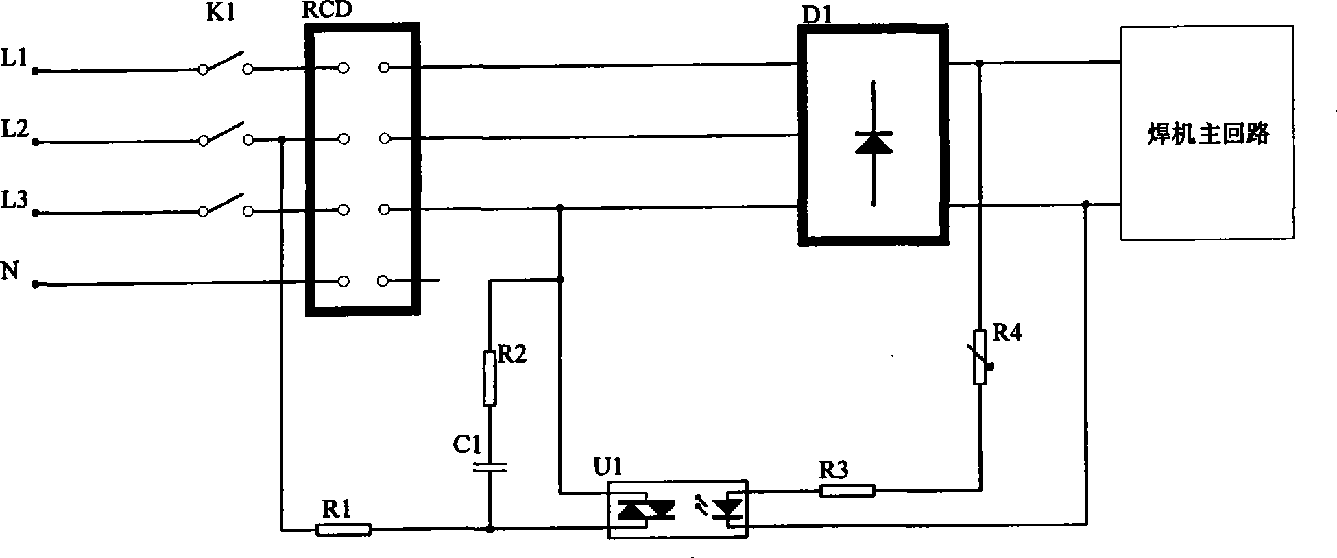
[0018] figure 1 Among them, the power supply is a three-phase four-wire system, and each phase L1, L2, L3 and N of the power supply is connected to the leakage circuit breaker RCD through the switch K1, and one of the output phase lines of the leakage circuit breaker RCD is connected to the secondary side of the optocoupler U1 Pin 4, pin 3 on the secondary side of U1 is connected to resistor R1, and the other end of R1 is connected to one of the input phase lines of the leakage circuit breaker RCD, L2; pin 4 on the secondary side of the optocoupler U1 is connected to resistor R2, and the other end of R2 is connected to a capacitor C1, the other end of C1 is then connected to pin 3 of the secondary side of U1; the alternating current output by each phase of the RCD output end of the leakage circuit breaker enters the rectification circuit D1 for rectification, and the positive output of D1 is connected to one end of the varistor R4, and the other end of the varistor R4 is connec...
Embodiment 2
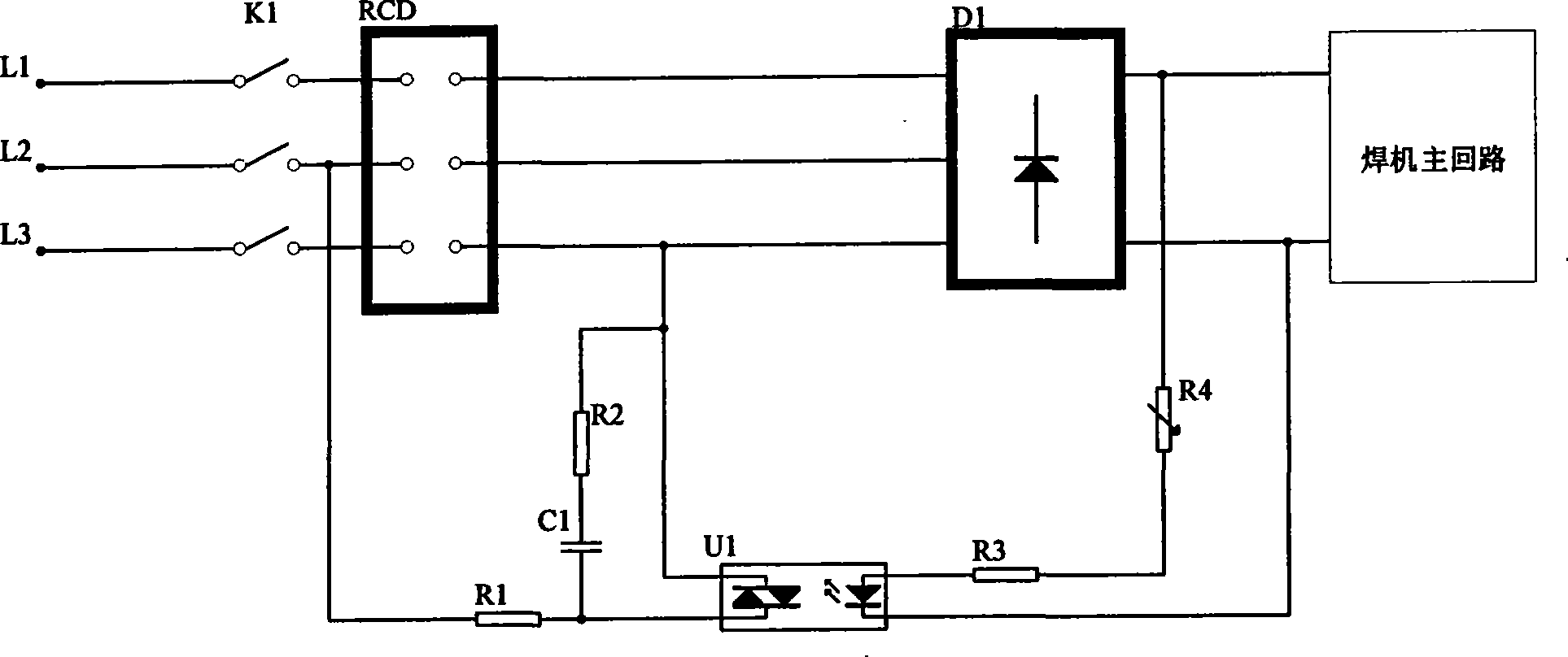
[0020] figure 2 Among them, the power supply is a three-phase three-wire system, and each phase L1, L2, L3 of the power supply is connected to the leakage circuit breaker RCD through the switch K1, and one of the output phase lines of the leakage circuit breaker RCD, L3, is connected to the secondary pin 4 of the optocoupler U1 , the No. 3 pin of the secondary side of U1 is connected to the resistor R1, and the other end of R1 is connected to one of the input phase lines of the leakage circuit breaker RCD, L2; the No. 4 pin of the secondary side of the optocoupler U1 is connected to the resistor R2, and the other end of R2 is connected to the capacitor C1, C1 The other end is connected to the No. 3 pin of the secondary side of U1; the alternating current output by each phase of the RCD output end of the leakage circuit breaker enters the rectification circuit D1 for rectification, and the positive output of D1 is connected to one end of the varistor R4, and the other end of th...
Embodiment 3
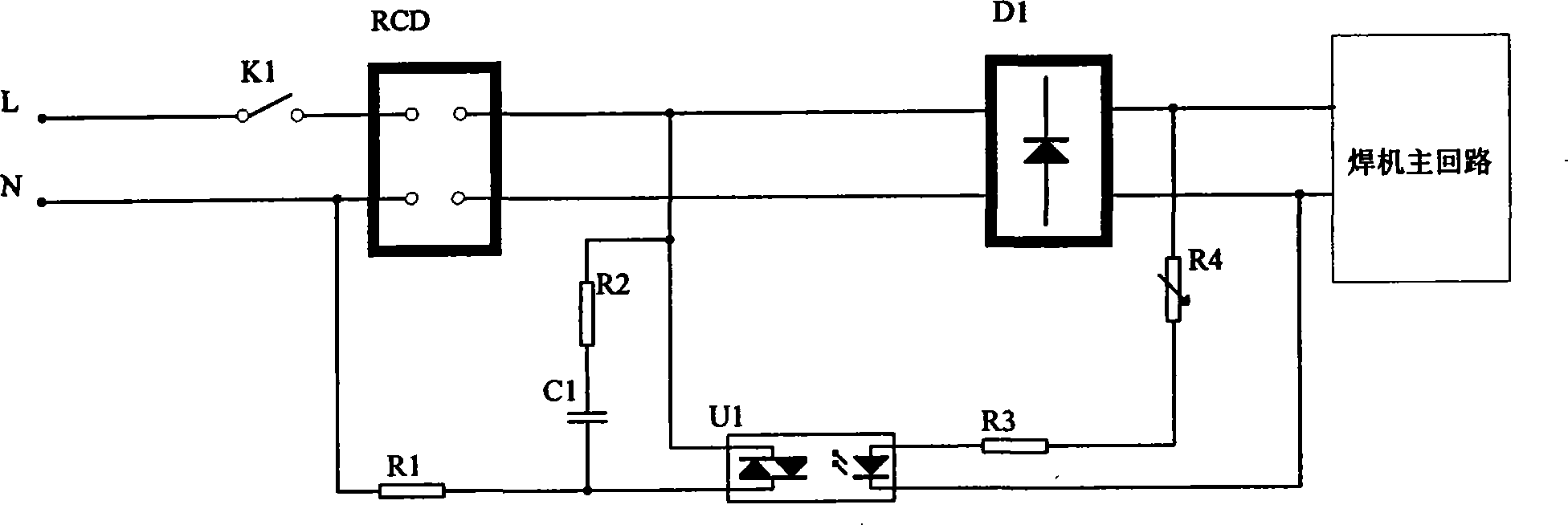
[0022] image 3 , the power supply is single-phase 220V, its L terminal is connected to the RCD input terminal of the leakage circuit breaker through the switch K1, and the N terminal is directly connected to the RCD input terminal of the leakage circuit breaker. The output terminal L of the leakage circuit breaker RCD is connected to the No. 4 pin of the secondary side of the optocoupler U1, the No. 3 pin of the secondary side of U1 is connected to the resistor R1, and the other end of R1 is connected to the neutral line N of the input terminal of the leakage circuit breaker RCD; the secondary side of the optocoupler U1 Pin 4 of RCD is connected to resistor R2, the other end of R2 is connected to capacitor C1, and the other end of C1 is connected to pin 3 of the secondary side of U1; the alternating current output from the output terminal L of the leakage circuit breaker RCD enters the rectifier circuit D1 for rectification, and the positive output terminal is connected to the...
PUM
 Abstract
Description
Claims
Application Information
 - Generate Ideas
- Intellectual Property
- Life Sciences
- Materials
- Tech Scout
- Unparalleled Data Quality
- Higher Quality Content
- 60% Fewer Hallucinations
Browse by: Latest US Patents, China's latest patents, Technical Efficacy Thesaurus, Application Domain, Technology Topic, Popular Technical Reports.
© 2025 PatSnap. All rights reserved.Legal|Privacy policy|Modern Slavery Act Transparency Statement|Sitemap|About US| Contact US: help@patsnap.com