Dynamic weeding device

A power and weeding technology, applied in the field of agricultural tools, can solve the problems of energy consumption, high labor intensity, low work efficiency, etc., and achieve the effects of enhanced stability, good stability and cost saving.

Inactive Publication Date: 2016-03-23
辛宗艳 +2
View PDF6 Cites 4 Cited by
  • Summary
  • Abstract
  • Description
  • Claims
  • Application Information

AI Technical Summary

Problems solved by technology

Among them, manual weeding is labor-intensive and low in work efficiency
Mechanical weeding improves the weeding efficiency. Generally, there are two methods: cutting the grass roots and digging them into the soil. However, both methods have disadvantages: the first method cuts the grass roots, because the roots of the weeds are still under the surface In the soil, weeds will re-grow after a suitable climate, which increases the weeding work again; the second is to dig out the grass roots, and to dig out the weed roots in the land, weeding tools must be inserted under the ground surface, so that although it is thoroughly Removes weeds, but severely disrupts the topsoil hierarchy, resulting in greater water loss from the soil
And mechanical weeding method needs to consume energy, the cost is higher
Chemical weeding is relatively time-saving and labor-saving. At present, manual sprayers or motorized weeds are usually applied to the weeds in the farmland. The disadvantages of these methods are that the herbicide application area is large and the dosage is large, which will cause the pesticide residues in agricultural products to exceed the standard. while seriously polluting the environment

Method used


Image

  • Dynamic weeding device
  • Dynamic weeding device
  • Dynamic weeding device

Examples


Embodiment Construction

[0032] The present invention will be further described in detail below in conjunction with the accompanying drawings, so that those skilled in the art can implement it with reference to the description.

[0033] It should be understood that terms such as "having", "comprising" and "including" as used herein do not entail the presence or addition of one or more other elements or combinations thereof.

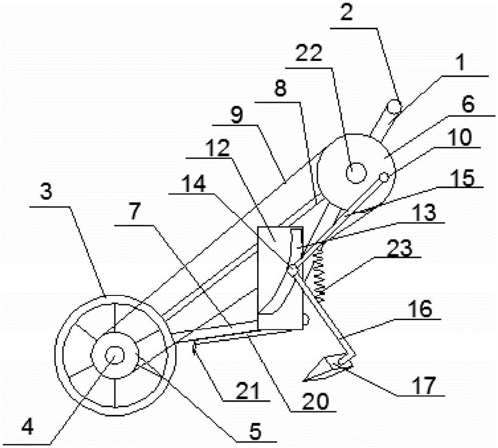
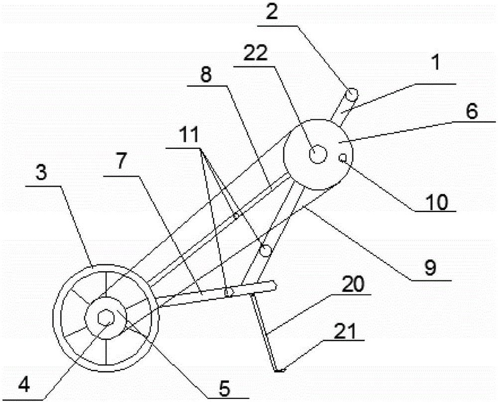
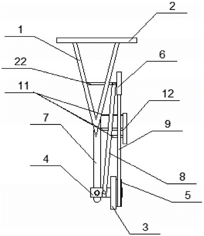
[0034] Such as Figure 1-4 Shown, the present invention provides a kind of power type weeding device, it comprises:

[0035]Bracket 1, which is a V-shaped structure, is integrally formed by two rods. The upper part of the bracket 1 is provided with a horizontal handrail 2. The upper part of the V-shaped bracket 1 is connected to the handrail 2 to form a triangle with good stability. The handrail 2 is convenient for driving the power weeding device. , the middle part is provided with a horizontal fixed rod 22, the first end of the fixed rod 22 is fixed on one of the rod bodies, t...


PUM


Abstract

The invention discloses a dynamic weeding device which comprises a bracket, a driving device, a plate body, a hoeing rod and a hoeing cutter, wherein a horizontal handrail is arranged in the upper part of the bracket, a horizontal fixed rod is arranged in the middle part of the bracket, a second end of the bracket is connected with a driven wheel, and a bump is arranged on the surface of the driven wheel; the driving device comprises a driving wheel, wherein a driving axle is arranged in the middle of the driving wheel, and a belt pulley is arranged at the second end of the driving axle in a sleeving manner; the surface at one side of the plate body is connected with a supporting column while an arc-shaped chute is formed on the surface at the other side of the plate body, and a slide block is arranged in the arc-shaped chute; a compression spring is connected between the hoeing rod and a crank; a strip-like through hole is formed on the second side face, toward the ground, of the hoeing cutter, sponge is paved on the second side face, and the hoeing cutter communicates with the hoeing rod to form a liquid medicine circulating path. The dynamic weeding device disclosed by the invention has the advantages of being simple in structure and economical and practical.

Description

technical field [0001] The invention relates to an agricultural tool. More specifically, the present invention relates to a powered weed control device. Background technique [0002] In addition to the crops consciously cultivated by farmers, there are many unwanted weeds in the crop fields. The weeds in the farmland have many hazards: competing for the nutrients, water and sunlight needed by the crops; hindering the ventilation and light transmission of the field; Promoted the occurrence of pests and diseases. Weeds directly or indirectly affect agricultural production, seriously affecting the yield, quality and quality of crops. [0003] At present, the control of weeds in farmland usually adopts manual weeding, mechanical weeding, biological control and chemical weeding. Wherein artificial weeding labor intensity is big, and work efficiency is low. Mechanical weeding improves the weeding efficiency. Generally, there are two methods: cutting the grass roots and digging...

Claims


Application Information

Patent Timeline
Patent Type & Authority Applications(China)
IPC IPC(8): A01D34/08A01M21/04
CPCA01D34/08A01M21/043
Inventor 覃建兵
Owner 辛宗艳
Why Eureka
Try Eureka