Laser transfer printing device and transfer printing head

A technology of laser transfer printing and transfer head, which is applied in the field of transfer printing head, and can solve problems such as being easily affected by electricity and magnetism, difficult servo control technology, and inability to adopt floating control methods.

Inactive Publication Date: 2008-10-15
ORMON CORP
View PDF1 Cites 0 Cited by
  • Summary
  • Abstract
  • Description
  • Claims
  • Application Information

AI Technical Summary

Problems solved by technology

[0011] However, since there are micron-order irregularities on the surface of such objects to be repaired (substrates of display devices, etc.), the distance between any position on the object to be repaired and the surface is always maintained at the micron level (for example, 1 to 20 μm). , is difficult for common servo control techniques using servo motors, linear motors, etc.
[0012] Moreover, such objects to be repaired (display devices, etc.) are easily affected by electricity and magnetism, and therefore, the floating control method using static electricity and magnetism cannot be adopted.

Method used


Image

  • Laser transfer printing device and transfer printing head
  • Laser transfer printing device and transfer printing head
  • Laser transfer printing device and transfer printing head

Examples


Embodiment Construction

[0128] Next, a preferred embodiment of the transfer head of the laser transfer device according to the present invention will be described in detail with reference to the drawings.

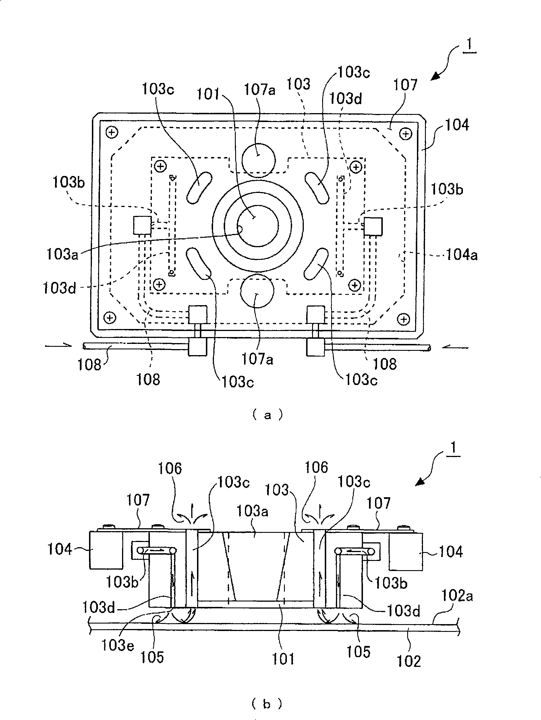
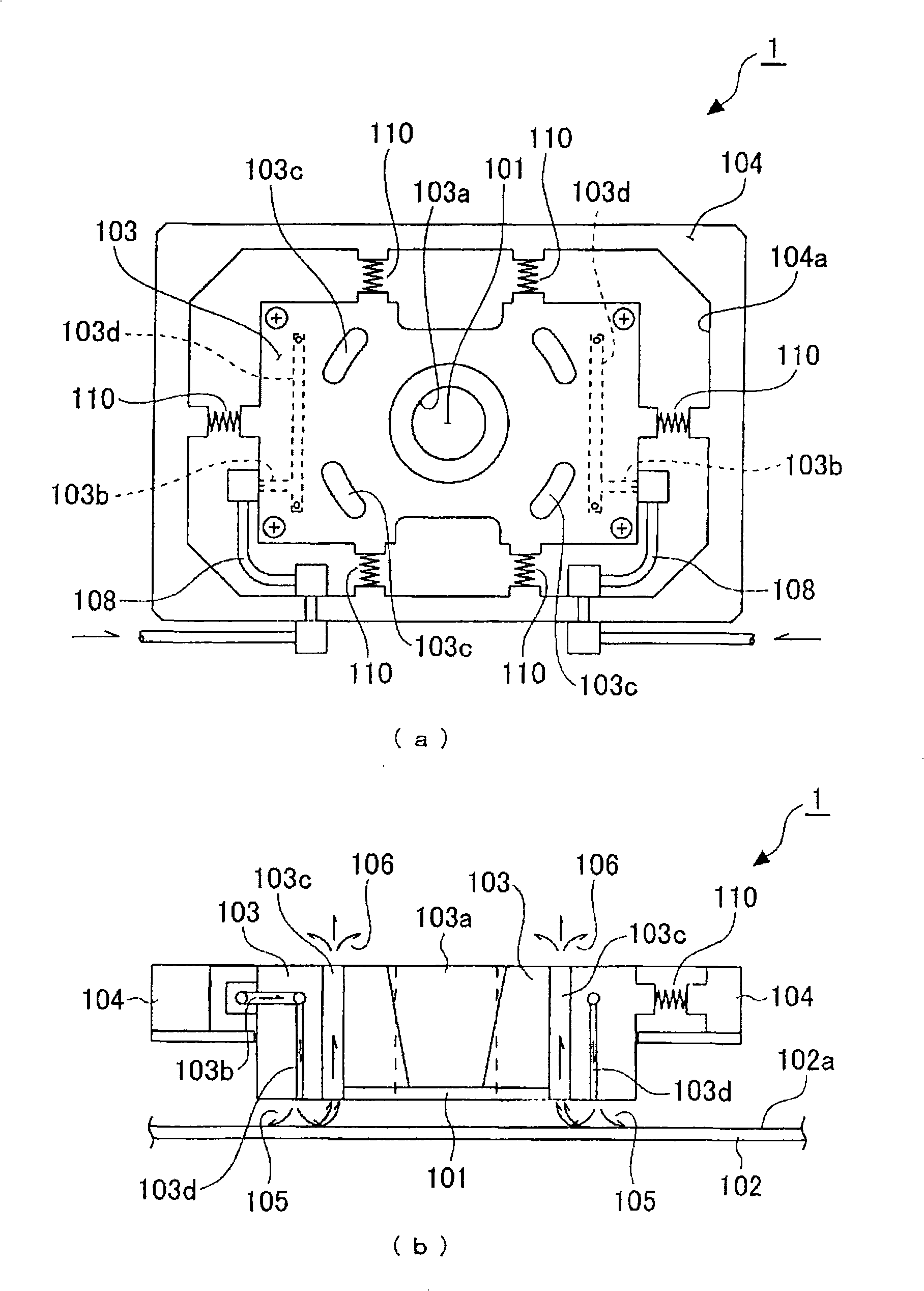
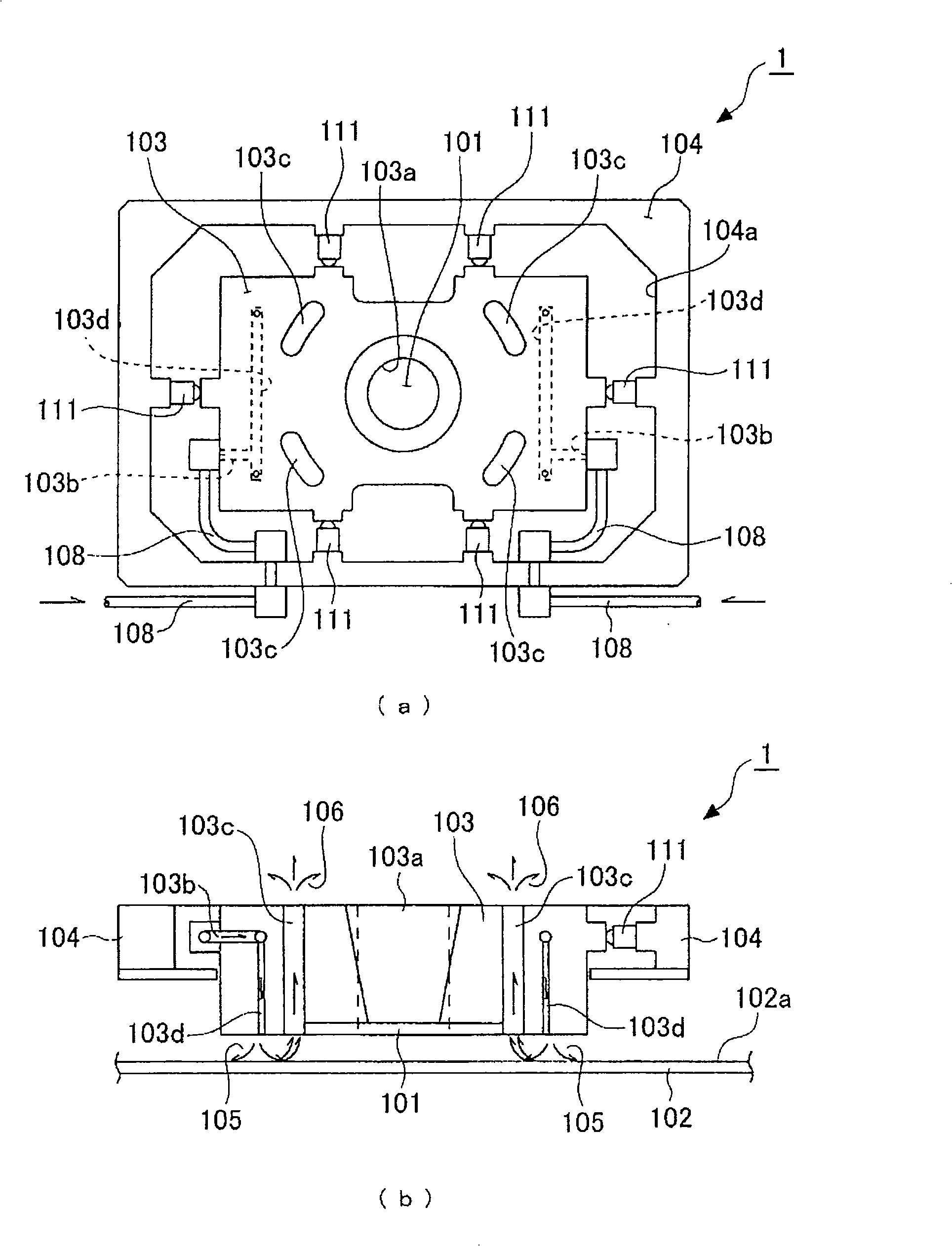
[0129] figure 1 (a), (b) are structural views showing the first embodiment of the transfer head of the laser transfer apparatus of the present invention. in addition, figure 1 (a) is a plan view, figure 1 (b) is a sectional view.

[0130] As can be seen from these figures, the transfer head 1 of the laser transfer apparatus places the transfer plate 101 so that the transfer material film (not shown) is opposed to the substantially horizontal transferred surface 102a of the transfer object 102. The transfer plate 101 is supported on the surface of a laser-transmissive plate-shaped small piece (for example, a plate-shaped small piece of quartz glass) with a fine and substantially constant gap between the two (in the figure). The bottom) is formed by covering a film of a transfer material (suc...


PUM


Abstract

The invention is related to a transfer printing head of the laser transfer printing device, wherein the laser transfer printing device, using the laser mending device as representation, is able to keep the distance between the film of the transfer printing material and the transfer printing object in the micron size all along. The transfer printing head has a holder which holds the transfer printing plate at the lower side and which is provided with a transfer printing window enabling the transfer printing plate to expose from the upper side, a transfer printing head mechanism which has a space for accommodating transfer printing plate holder and gives the position standards for the horizontal direction and the vertical direction, a holder bearing mechanism which bears the transfer printing plate holder in the space for accommodating the transfer printing plate held in the transfer printing head mechanism to be able to move up and down instead of horizontal displacement with respect to the transfer printing head mechanism, and a transfer printing plate floating device which sprays gas to the lower part of the transfer printing plate holder in order to float the transfer printing plate and the transfer printing holder together with respect to the transferred printing surface, wherein a gas spray-hole is configured around the periphery of the transfer printing plate but below the transfer printing plate holder.

Description

technical field [0001] The present invention relates to a transfer head of a laser transfer device suitable for use as a laser repair device for repairing defects in circuit patterns in display devices such as liquid crystal displays and plasma displays, for example. Background technique [0002] Conventionally, in display devices such as liquid crystal displays and plasma displays, a laser repairing device using a laser CVD method has been used to repair defects in circuit patterns. [0003] The laser repair device using the laser CVD method uses the chemical vapor phase growth method of the laser. Specifically, the laser is irradiated to the substrate placed in the raw material gas, and the raw material gas is formed by promoting the chemical and physical reaction of the raw material gas on the laser irradiation surface. The film grows on the repair site on the substrate. [0004] However, for the laser repairing device using such a conventional laser CVD method, the foll...

Claims


Application Information

Patent Timeline
Patent Type & Authority Applications(China)
IPC IPC(8): G02F1/13G09F9/30B23K26/00G02F1/1343G02F1/1345G09F9/00
CPCB23K26/082G02F1/1303
Inventor 池泽利明
Owner ORMON CORP
Why Eureka
Try Eureka