Vehicle mounted type automobile fault diagnostic apparatus

A technology of automobile fault diagnosis instrument, which is applied in the direction of electrical testing/monitoring, etc. It can solve the problems of difficult vehicle engine ECU system compatibility, difficulty in developing automobile fault diagnosis instrument, and high maintenance cost, so as to increase the scope of use and save research and development costs , the effect of compact system

Inactive Publication Date: 2008-10-15
杨思念
0 Cites 23 Cited by

AI-Extracted Technical Summary

Problems solved by technology

[0005] In order to overcome the difficulties in the development of the existing automobile fault diagnosis instrument, the compatibility with various vehicle engine ECU systems, high cost and high maintenance cost, the pr...

Abstract

The invention provides an on-board automobile failure diagnosis instrument, belonging to the field of automobile electronic equipment technique. The on-board automobile failure diagnosis instrument of the invention is characterized in that the diagnosis instrument comprises a signal processing module which is connected with a diagnosis joint of an automobile diagnosis base by a diagnosis interface, a communication control module, a communication interface module, a memory module, a main control module, a liquid crystal display module and a power supply module. The on-board automobile failure diagnosis instrument provided by the invention has independent CPU, low cost and good diagnosis effect, and can comply with the failure diagnosis requirements of various automobile engines.

Application Domain

Technology Topic

Image

  • Vehicle mounted type automobile fault diagnostic apparatus
  • Vehicle mounted type automobile fault diagnostic apparatus

Examples

  • Experimental program(1)

Example Embodiment

[0020] The principle of the present invention will be described in detail below in conjunction with the accompanying drawings:
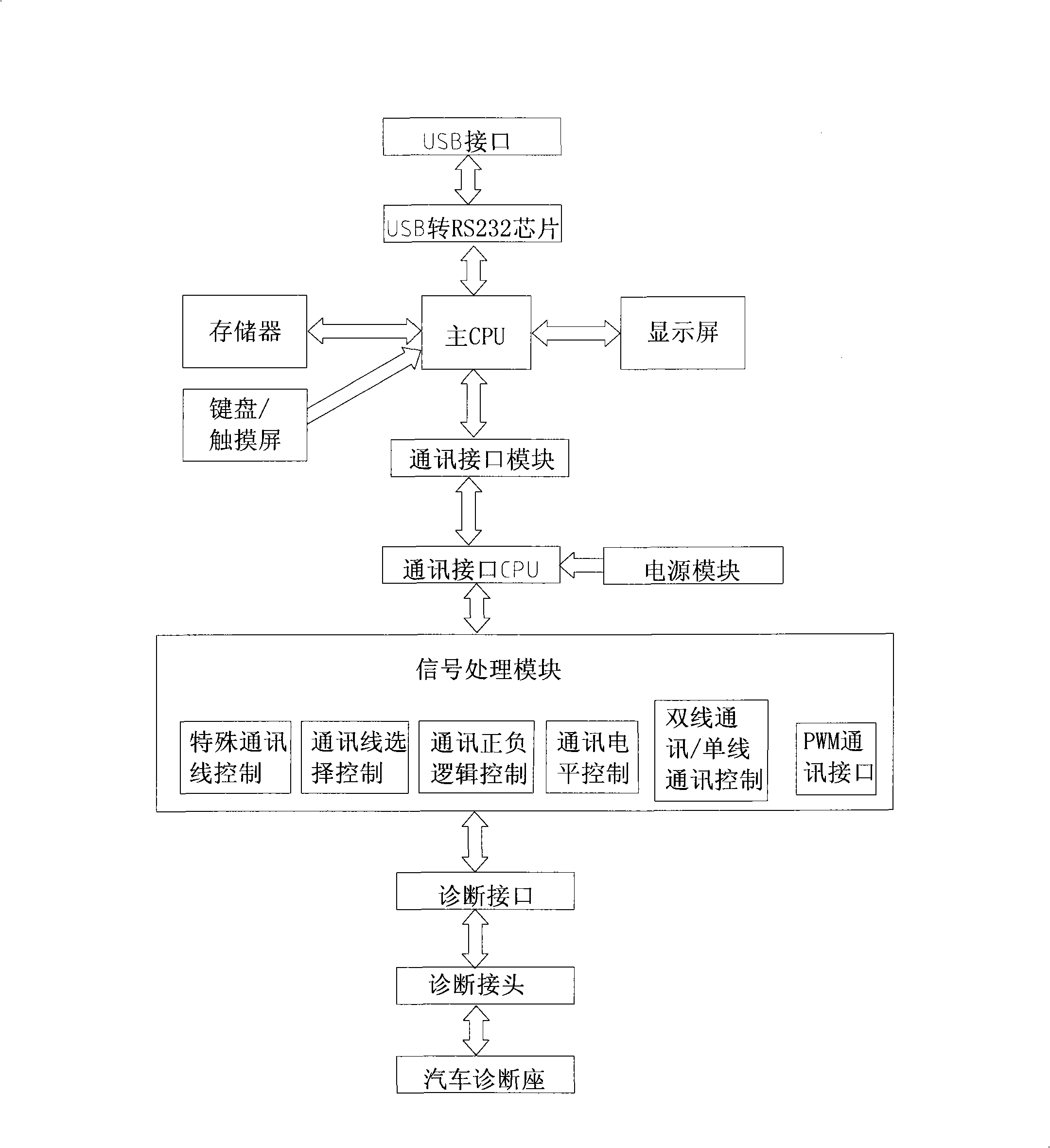
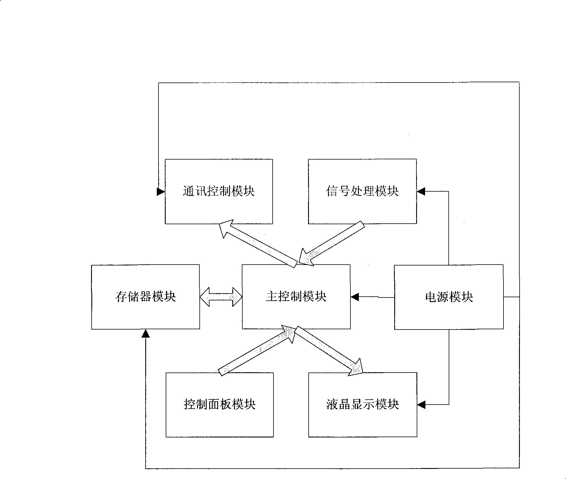
[0021] Refer to the attached figure 1 and 2 , the vehicle-mounted vehicle fault diagnostic instrument of the present embodiment, the diagnostic instrument includes:
[0022] The signal processing module is connected to the diagnostic connector of the vehicle diagnostic socket through the diagnostic interface, which is connected to the diagnostic connector through the standard serial connector DB26, and the serial connector is used as a diagnostic interface for communicating with each sensor. The signal processing module adopts conventional modules with communication positive and negative logic control, communication level control, two-wire communication/single-wire communication control, communication line selection control, PWM communication interface and special communication line control.
[0023] Communication control module: used for the selection of the above-mentioned signal processing module and controlling the electrical characteristics of the communication line. The communication interface CPU is used as the communication control module, and the AT89S52 chip can be selected.
[0024] Communication interface module: used for the communication between the above-mentioned communication control module and the main control module, so as to realize various physical links between the system and the vehicle communication, and its selection mainly matches the above-mentioned communication control module.
[0025] Memory module: used to store vehicle diagnostic programs and system operating programs for calling by the main control module. This diagnostic instrument chooses MBM29DL640 memory chip, 8M capacity;
[0026] The main control module selects MS-37015 as the core logic control device, that is, the main CPU, which is used to receive the input signal of the above-mentioned communication interface module, output it after processing, and read the diagnostic program and system operation program of the above-mentioned memory module.
[0027] The liquid crystal display module adopts 240*160GRAPH monochrome LCD display module, which is used to receive and display the output information of the main control module, for the reference of drivers and passengers.
[0028] The power supply module is a commonly used wide voltage input DC level conversion module, which is powered by a vehicle-mounted lead-acid battery. The power supply module outputs 3.3V, 5V and 12V stable voltages for the above modules.
[0029] In addition, this embodiment also includes a control panel module for inputting data to the main control module, so as to control the main control module to read corresponding diagnostic programs and system operation programs from the memory module. The control panel module can optionally have 4 A keypad with a direction key, a return key, a confirmation key and 10 numeric keys. At the same time, in order to consider the degree of integration, the integration of the control panel module and the above-mentioned liquid crystal display module is realized by using a touch screen. Of course, the control panel itself and the touch screen can be used, and it is separated from the above-mentioned liquid crystal display module.
[0030] Considering that the drivers and passengers may not pay attention to the LCD screen, in order to realize the feedback of diagnostic information, especially fault information, to the drivers and passengers, the present invention also includes a speaker for receiving the sound signal of the main control module, Provide voice prompts for vehicle status and faults.
[0031] In addition, in order to upgrade the system diagnostic program and running program, the present embodiment is also provided with a software upgrade USB interface, which is connected with the main CPU through a USB to RS232 chip, and the USB to RS232 chip adopts CP2102 commonly used in China at present.

PUM

no PUM

Description & Claims & Application Information

We can also present the details of the Description, Claims and Application information to help users get a comprehensive understanding of the technical details of the patent, such as background art, summary of invention, brief description of drawings, description of embodiments, and other original content. On the other hand, users can also determine the specific scope of protection of the technology through the list of claims; as well as understand the changes in the life cycle of the technology with the presentation of the patent timeline. Login to view more.

Similar technology patents

Classification and recommendation of technical efficacy words

  • Reduce R&D costs
  • Compact system

Electromagnetic coupling ultrasonic automatic detection device and method for wheel tread and wheel rim

PendingCN107132282AEliminate the influence of detection blind zoneReduce R&D costsAnalysing solids using sonic/ultrasonic/infrasonic wavesRadio frequencyBody waves
Owner:BEIJING HAIDONGQING ELECTRICAL & MECHANICAL EQUIP +1
Why Eureka
Try Eureka