Mixer for concrete

A technology of concrete mixer and mixing cylinder, which is used in mixer accessories, mixers, cement mixing devices, etc.

Active Publication Date: 2012-06-20
加莱蒂工程机械有限责任公司
View PDF6 Cites 0 Cited by
  • Summary
  • Abstract
  • Description
  • Claims
  • Application Information

AI Technical Summary

Problems solved by technology

[0015] Moreover, the operation of lifting heavy objects will seriously endanger the safety of operators

Method used


Image

  • Mixer for concrete
  • Mixer for concrete
  • Mixer for concrete

Examples


Embodiment Construction

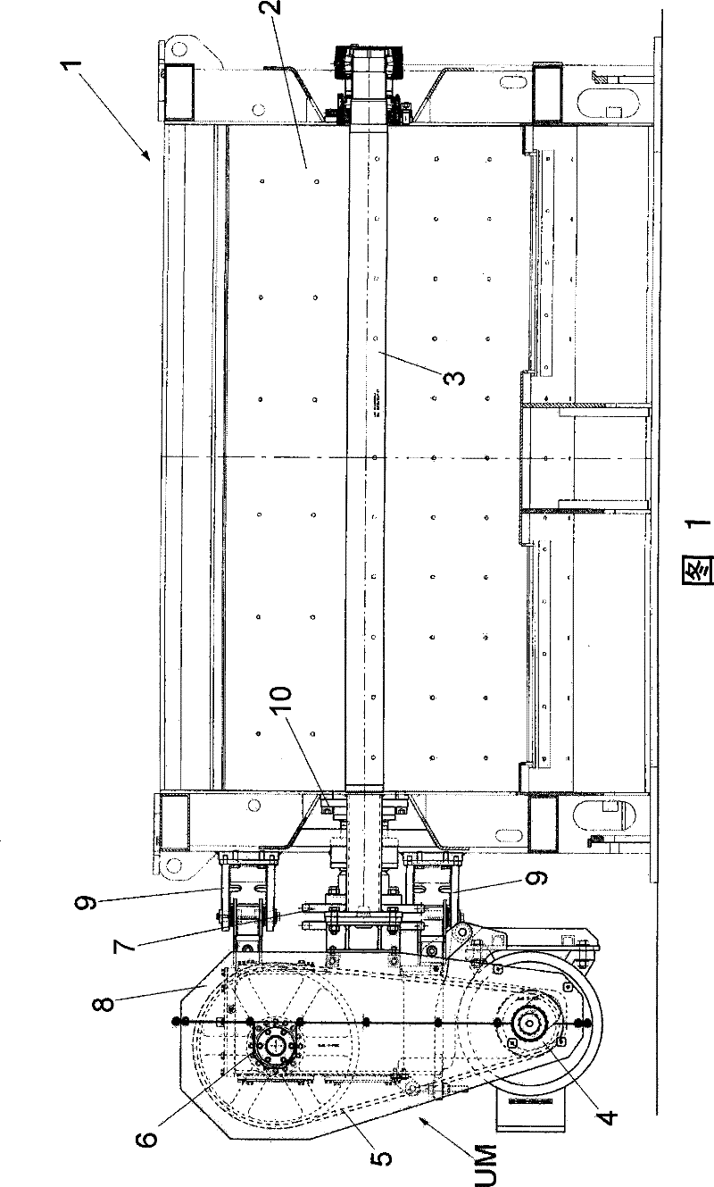
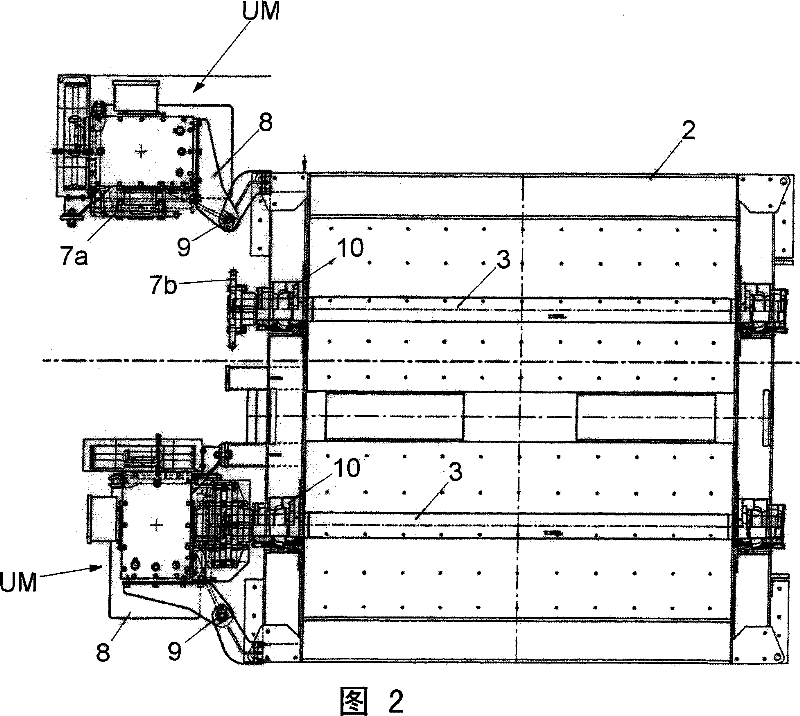
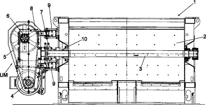
[0038] According to the above illustration, the conventional component of the mixer 1 is a rectangular mixing tank 2 equipped with one or several rotating mixing shafts 3 supported horizontally between two transverse sides.

[0039] Each agitator shaft 3 is driven by a corresponding motor system UM consisting of an electric motor 4 connected by a conveyor belt 5 to a gear motor 6 which in turn is connected to the top end of the corresponding agitator shaft 3 via a joint 7 .

[0040] All the components of the above-mentioned engine system UM are fixed to the same frame 8 , which is fixed on the outside of the load-bearing side of the mixing tank 2 by one or several fasteners, namely hinges 9 .

[0041] As mentioned above, the frame 8 and the parts of the engine system UM can be shifted and moved from the working position (in close contact with the side of the mixing tank) to the non-working position (deviating from the above-mentioned side) by using the hinge 9, so that the stir...


PUM


Abstract

The invention relates to a stirrer for concrete, comprising a rectangular stirring cylinder which is provided with one or a plurality of stirring shafts inside, the rotation of each of which is driven by a corresponding engine located out of the stirring cylinder; the engine system is composed by connecting an electromotor, a gear electromotor with an intermediate gear connected to the top of the corresponding stirring shaft via necessary connection components; the invention has the characteristic that the electromotors and the corresponding gear electromotor of each engine system are all fixed on the same support framework, the framework is hung at the side of the stirring cylinder via one or a plurality of hinges; the stirrer for concrete has the characteristics of simple and fast maintenance and repairing.

Description

technical field [0001] The invention relates to a concrete mixer, which is characterized by simple and fast maintenance and is used for mixing concrete, powder, dry and semi-dry granules. Background technique [0002] As we all know, the traditional mixer used in different industries, especially the construction industry, is composed of a large rectangular mixing tank, the inner wall is cylindrical or omega-shaped, and there are one or several stirring shafts in the tank to stir and put them into the tank in a horizontal direction. aggregate. [0003] The above-mentioned stirring shaft is equipped with a specially designed radioactive stirring knife to improve the efficiency of stirring the aggregate. [0004] The lateral sides of the mixer bowl are fitted with shaft end fittings for insertion of the mixer shaft, containing appropriate gears and seals. [0005] The motor system for rotating each agitator shaft is mounted externally on one or both lateral sides of the agit...

Claims


Application Information

Patent Timeline
Patent Type & Authority Patents(China)
IPC IPC(8): B01F7/04B01F15/00B28C5/14
CPCB28C5/0831B01F2015/00584B28C5/146B01F7/047B01F15/00922B01F15/00435B01F27/706B01F35/3211B01F35/30B01F35/10
Inventor 保罗·加莱蒂
Owner 加莱蒂工程机械有限责任公司
Why Eureka
Try Eureka