Flexible driving structure of ultra-large-capacity centrifugal machine

A driving structure and centrifuge technology, which is applied in the direction of centrifuges, can solve the problems of centrifuge production vibration, ineffective repair and maintenance, and spindle deformation, so as to reduce manual debugging time, facilitate assembly and disassembly, and fast. Eliminates the effects of production vibration

Pending Publication Date: 2022-05-24
长沙英泰仪器有限公司
View PDF0 Cites 0 Cited by
  • Summary
  • Abstract
  • Description
  • Claims
  • Application Information

AI Technical Summary

Problems solved by technology

[0005] This application proposes a flexible driving structure for a super-large-capacity centrifuge to solve the problem that the prior art proposed in the above-mentioned background technology does not consider the centrifuge operating state and the production vibration under the unbalanced tolerance state, and the problem of exceeding 16000ml and weighing more than 35kg The huge kinetic energy brought by the 6000×g centrifugal force generated by the centrifuge rotor at the speed of 4200r / min and the huge twisting force generated during the speed up and down will cause the main shaft to deform or twist, making it impossible to effectively repair and maintain the problem

Method used


Image

  • Flexible driving structure of ultra-large-capacity centrifugal machine
  • Flexible driving structure of ultra-large-capacity centrifugal machine
  • Flexible driving structure of ultra-large-capacity centrifugal machine

Examples


Embodiment Construction

[0027] The technical solutions in the embodiments of the present application will be clearly and completely described below with reference to the drawings in the embodiments of the present application. Obviously, the described embodiments are only a part of the embodiments of the present application, rather than all the embodiments.

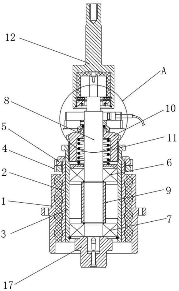
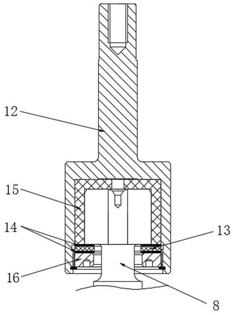
[0028] see figure 1 As shown in the figure, a flexible drive structure of a super-capacity centrifuge includes a drive base 1, a damping seat 2 is arranged in the driving base 1, a bearing seat 3 is arranged in the damping seat 2, and the upper sides of the bearing seat 3 and the damping seat 2 are both A round nut 4 is installed, a gland nut 5 is arranged on the round nut 4, an upper bearing 6 and a lower bearing 7 are installed in the bearing seat 3, a main shaft 8 is installed in the bearing seat 3, and the main shaft 8 penetrates the upper bearing 6 and the lower bearing 7 There is a bearing top sleeve 9 between the upper bearing 6 and the lo...


PUM


Abstract

The invention discloses an ultra-large-capacity centrifugal machine flexible driving structure which comprises a driving base, a damping seat is arranged in the driving base, a bearing seat is arranged in the damping seat, round nuts are installed on the two sides of the upper portion of the bearing seat and the two sides of the upper portion of the damping seat, gland nuts are arranged on the round nuts, and an upper bearing and a lower bearing are installed in the bearing seat. A main shaft is installed in the bearing seat and penetrates through inner rings of the upper bearing and the lower bearing, a bearing top sleeve is arranged between the upper bearing and the lower bearing, the main shaft is sleeved with the bearing top sleeve, a shaft protecting sleeve is arranged at the top of the bearing seat and sleeved with the main shaft, and a compression spring is connected between the shaft protecting sleeve and the upper bearing. By improving the treatment process and structure of the flexible main shaft and the design of the damping seat, the use requirements of the ultra-large-capacity centrifugal machine are met, the stability is improved, maintenance is convenient, and the service life is prolonged.

Description

technical field [0001] The invention relates to the technical field of centrifuge drive structures, in particular to a flexible drive structure of a super-capacity centrifuge. Background technique [0002] Centrifuges with a single-machine capacity of more than 1000ml are defined as large-capacity centrifuges, while those exceeding 6000ml are defined as ultra-large-capacity centrifuges. With the development of biopharmaceuticals and modern medical technology, especially the application of new technologies such as traditional Chinese medicine, Chinese patent medicine, polymer technology biopharmaceutical and blood pretreatment technology improved under modern technical conditions, and the mandatory requirements of the national standard system. Extracting high-purity APIs through physical separation is the best solution for biopharmaceutical technology. The centrifugal force generated by the centrifuge is the fastest, most efficient and most accurate solution. Therefore, in ...

Claims


Application Information

Patent Timeline
Patent Type & Authority Applications(China)
IPC IPC(8): B04B9/08B04B15/06
CPCB04B9/08B04B15/06
Inventor 徐昌平张海兵李前程
Owner 长沙英泰仪器有限公司
Why Eureka
Try Eureka