

Continuous pugging extruder rotor
A technology of extruder and rotor, which is applied in the field of continuous mixing extruder rotor, which can solve the problems of enlarged mandrel, large screw length-to-diameter ratio, and increased difficulty of assembly, so as to achieve the effect of improving rigidity
Inactive Publication Date: 2008-10-22
恒力石化股份有限公司
View PDF0 Cites 15 Cited by
- Summary
- Abstract
- Description
- Claims
- Application Information
AI Technical Summary
Problems solved by technology
However, in order to achieve the required degree of plasticization, the length-to-diameter ratio of the screw is relatively large (generally 15-56); in this way, the material selection and processing of the mandrel increase the difficulty; the assembly difficulty of the screw combination also increases
Method used
View moreImage
Smart ImageViewing Examples

Examples
Embodiment Construction
Login to View More PUM
 Abstract
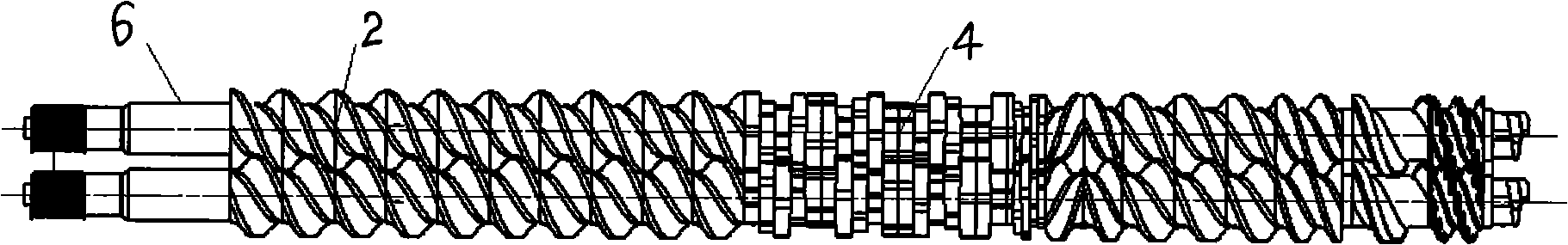
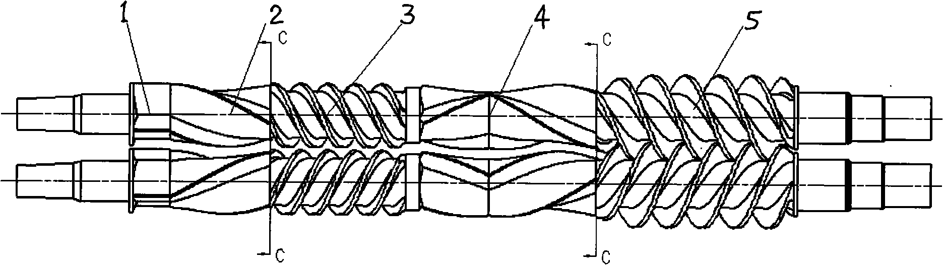
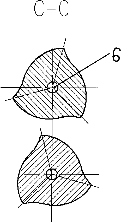
The invention relates to a birotor for a continuous mixing extruding granulating set, in particular to a rotor for a continuous mixing extruder; each rotor is provided with a feeding section and a mixing section; the mixing section consists of positive multi-edge screw and negative multi-edge screw; an integral structural rotor greatly improves the rigidness of the rotor and simultaneously omits the processing of a core shaft. The feeding section adopts engaged multiple threads or semi-engaged multiple threads to carry out compulsory feeding on materials; the mixing section consists of a positive section of multi-edge screw and a negative section of multi-edge screw; the positive section pushes the materials forwards; while the negative section leads the materials to move backwards and to be ceaselessly extruded, cut, dispersed, mixed and pushed in a plurality of relatively independent mixing spaces. The birotor of the invention has extremely high mixing and plasticizing actions; the ratio of long diameter is usually smaller than 12; the birotor of the invention can be broadly applied to a continuous mixing extruding granulating system for the materials with thermoplasticity or high viscosity or for pasty materials.
Description
Continuous mixing extruder rotor 1. Technical field The invention relates to a continuous mixing extrusion granulation unit, in particular to a double rotor of the granulation unit. 2. Background technology The mixing extrusion granulation unit is one of the most important equipment for ethylene engineering in the petrochemical industry. The screw (called the rotor in the continuous mixing extruder unit) is the most indispensable core component of the mixing extrusion granulation unit. Its function is to convey, compress, knead and plasticize, measure and build pressure and extrude the added materials; provide the melt with good kneading and plasticization, uniform temperature, stable pressure and stable extrusion volume for the next process; It is a functional component that completes the mixing and plasticizing of polymers, and is the key to evaluating the performance of the unit. In the kneading extrusion granulation unit, the traditional screw rotates in the same di...
Claims
Login to View More Application Information
Patent Timeline
 Patent Type & AuthorityApplications(China)
IPC IPC(8): B29B7/48
CPCB29C47/6025B29C47/622B29C47/6037B29C47/6056B29B7/465B29B7/482B29B7/483B29C48/40B29C48/535B29C48/55B29C48/57B29C48/645
Inventor何桂红刘明达张福国刘鑫传
Owner恒力石化股份有限公司