
Method and grinding machine for profiling a grinding tool

A technology of profile grinding and grinding tools, which is applied to the parts of grinding machine tools, manufacturing tools, grinding/polishing equipment, etc., and can solve the problems of expensive and time-consuming grinding processes

Active Publication Date: 2008-10-29
KAPP GMBH & CO KG WERKZ MASCHFAB
View PDF0 Cites 19 Cited by
  • Summary
  • Abstract
  • Description
  • Claims
  • Application Information

AI Technical Summary

Problems solved by technology

[0007] The disadvantage is that a corresponding amount of time is required for this, so that the grinding process is correspondingly expensive

Method used


Image

  • Method and grinding machine for profiling a grinding tool
  • Method and grinding machine for profiling a grinding tool

Examples


Embodiment Construction

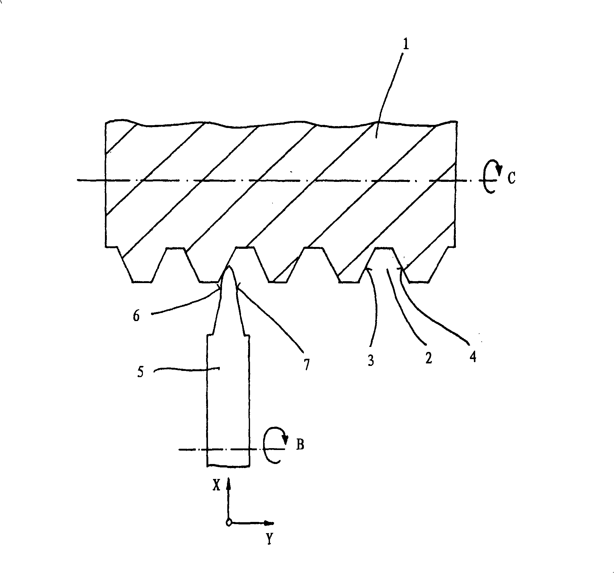
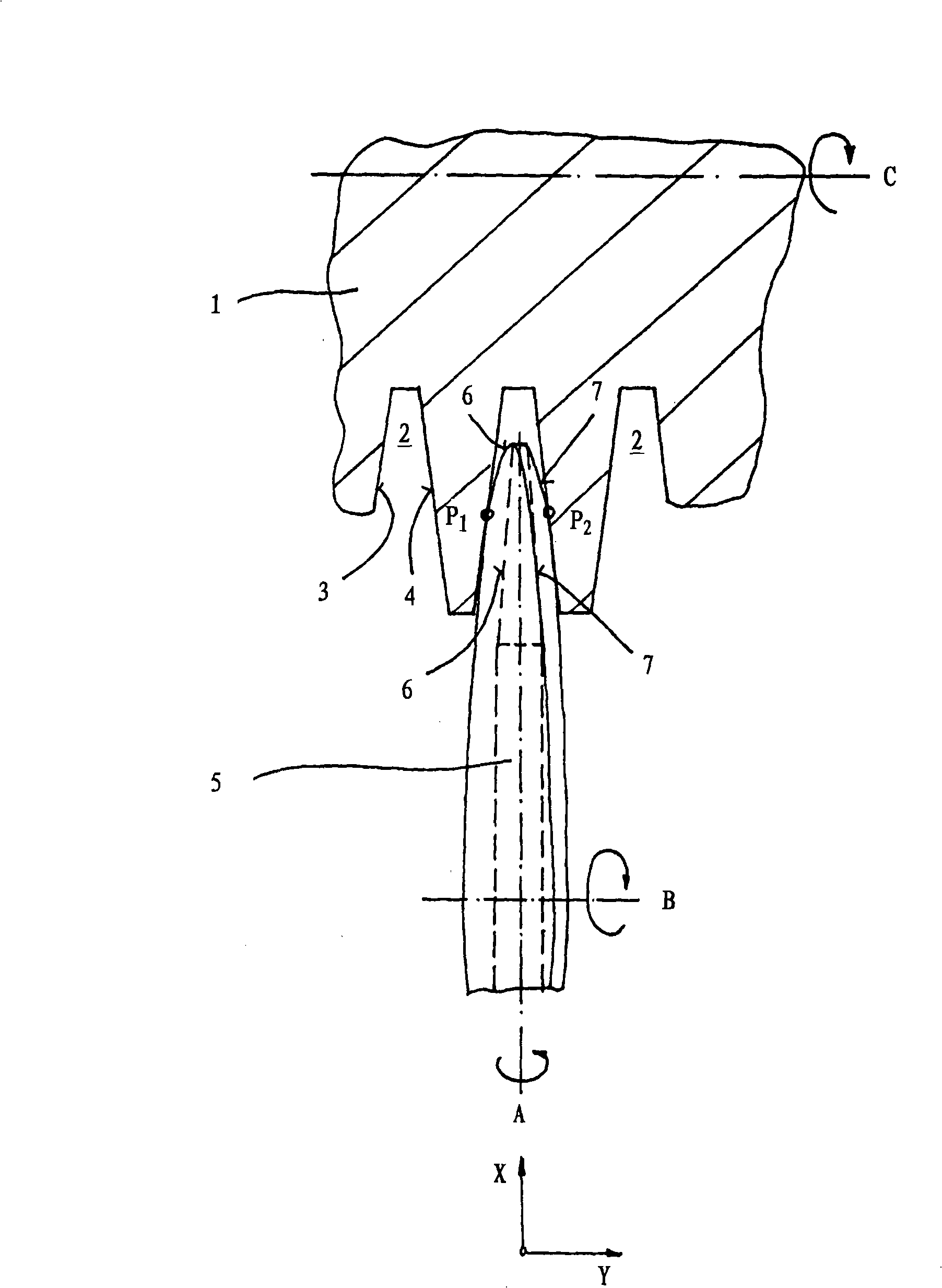
[0029] exist figure 1 The per se known row-by-row dressing of the grinding tool 1 in the form of a grinding screw can be seen in FIG. In axial section, the grinding screw 1 has a tooth profile 2 which is determined or limited by two tooth flanks 3 and 4 . The first tooth flank 3 and likewise the second tooth flank 4 have a largely rectilinear shape in axial section, but corrections are superimposed on the largely rectilinear course in order to obtain a corresponding coherence in the finished gear wheel. Yoke profile. The two tooth flanks 3 and 4 lie opposite one another as can be seen.

[0030] In order for the tooth profile 2 to have the desired precise shape, a dressing process is necessary, for which a disk-shaped dressing tool 5 is provided. In axial section, the dressing tool 5 has the figure 1 The shape described in , namely a first grinding surface 6 and a second grinding surface 7 , which are used to cooperate with the first tooth flank 3 or the second tooth flank ...


PUM


Abstract

The invention relates to a method and machine for the dressing of a grinding tool ( 1 ), which has at least one tooth-shaped profile ( 2 ) with a first flank ( 3 ) and an opposing second flank ( 4 ). A disk-shaped dressing tool ( 5 ) used for dressing of the grinding tool ( 2 ) has a first abrasive area ( 6 ) and a second abrasive area ( 7 ). To allow a faster and thus more economical dressing of the grinding tool, the first abrasive area ( 6 ) contacts the first flank ( 3 ) and the second abrasive area ( 7 ) contacts the second flank ( 4 ) simultaneously, and the disc-shaped dressing tool ( 5 ) and / or the grinding tool ( 1 ) are pivoted relatively to another around an axis (A) being arranged perpendicular to the axis of rotation (C) of the grinding tool ( 1 ), so that both flanks ( 3, 4 ) are dressed simultaneously.

Description

technical field [0001] The invention relates to a method for profiling a grinding tool having at least one toothed profile in axial section, wherein the toothed profile has a first tooth flank and a surface opposite to the first tooth The second tooth flanks arranged, they constitute the boundary of the tooth profile, wherein when forming the profile of the grinding tool, there is a disc-shaped dressing tool with a first grinding surface and a second grinding surface between the grinding surface and the tooth profile The guides are guided relative to the grinding tool in the presence of a relative velocity between them, so that the desired shape of the tooth flank is obtained, wherein the first grinding surface is assigned to the first tooth flank and the second grinding surface is assigned to the second tooth flank. Furthermore, the invention relates to a grinding machine for carrying out the method. Background technique [0002] The final machining step plays an important...

Claims


Application Information

Patent Timeline
IPC IPC(8): B23F19/02B24B53/07B24B53/12
CPCB24B53/085B23F23/1225B23F5/04B24B53/12
Inventor J·洛佩斯
Owner KAPP GMBH & CO KG WERKZ MASCHFAB
Learn More