Cutting device

A cutting and attracting device technology, applied in the directions of transportation and packaging, thin material processing, printing, etc., can solve the problem that the sheet does not have a predetermined length, and achieve the effect of preventing unstable behavior

Inactive Publication Date: 2008-10-29
KOMORI CORP
View PDF0 Cites 8 Cited by
  • Summary
  • Abstract
  • Description
  • Claims
  • Application Information

AI Technical Summary

Problems solved by technology

Therefore, in some cases, the cutting position of the web varies, and this variation may cause the cut sheet to not have a single predetermined length

Method used


Image

  • Cutting device
  • Cutting device
  • Cutting device

Examples


no. 1 example

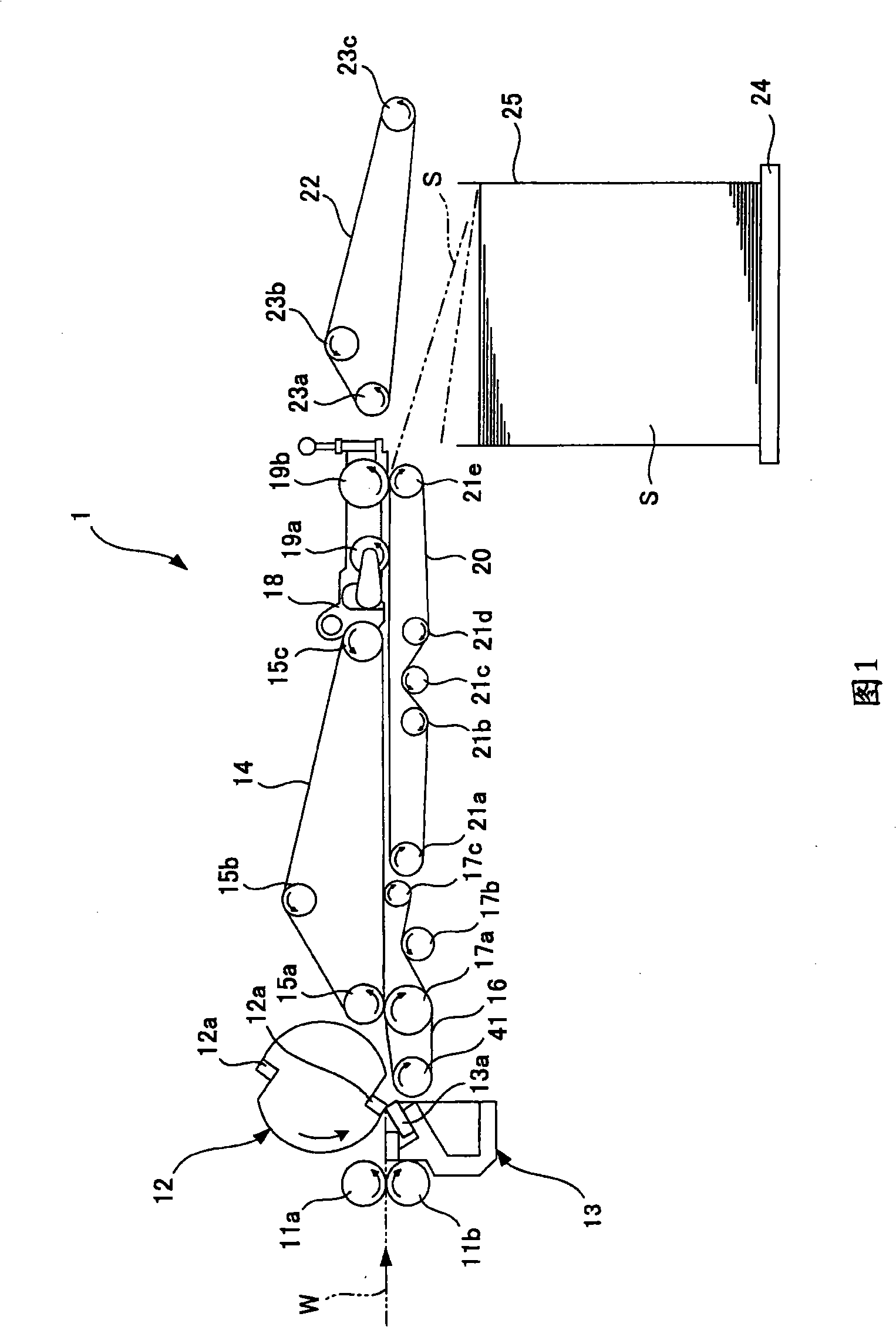
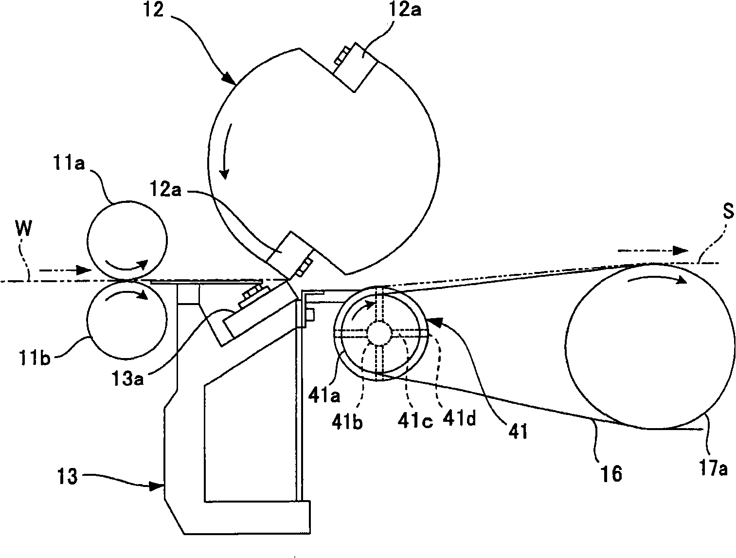
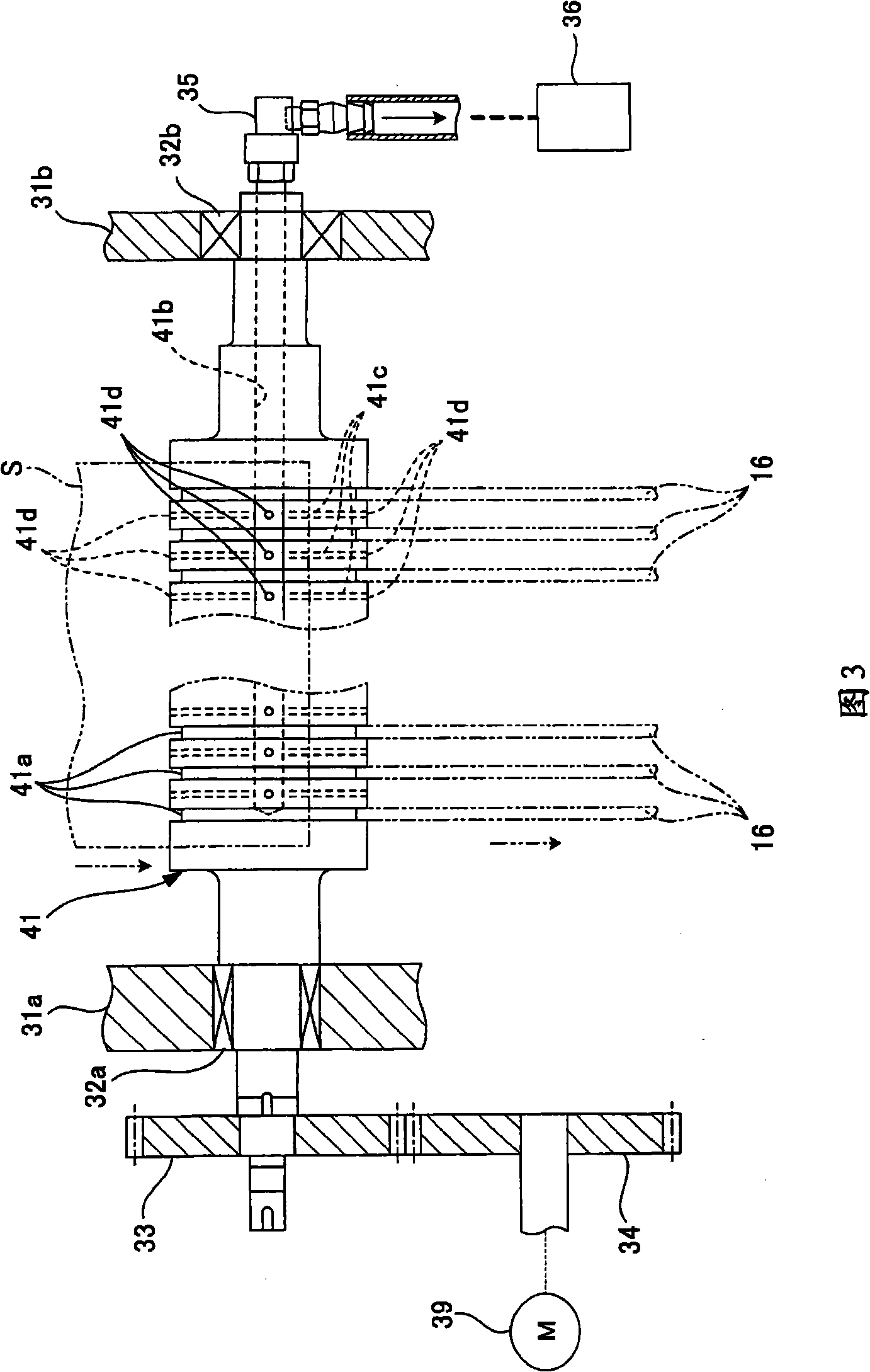
[0032] FIG. 1 is an overall schematic diagram of a cutting device according to a first embodiment of the present invention. figure 2 It is an enlarged view of main parts of the cutting device shown in FIG. 1 . Figure 3 is figure 2 The top view of the main part of the cutting device shown.

[0033] As shown in FIG. 1 , the web rotary printing press not shown in the figure includes a cutting device 1 . The cutting device is configured to cut the printed web W dried and cooled after printing into a predetermined length of sheet S, and then stack the resulting sheet while flattening the edge of the sheet.

[0034] The cutting device 1 includes a pair of nip rollers 11a and 11b rotatably supported at upstream positions thereof in a direction in which a roll paper is conveyed (hereinafter referred to as "roll paper conveyance direction"). The nip rollers 11a and 11b are arranged to be vertically opposed to each other so that the nip rollers can nip the web being transported. At ...

no. 2 example

[0055] Figure 4 It is an enlarged view of main parts of the cutting device according to the second embodiment of the present invention. Figure 5 is Figure 4 The top view of the main part of the cutting device shown. In addition, those elements having the same or similar structure and function as those of the cutting device of the first embodiment are denoted by the same reference numerals, and their repeated descriptions are omitted.

[0056] Such as Figure 4 As shown, the web rotary printing machine not shown in the figure includes a cutting device 2 for cutting the printed web W which is dried and cooled after printing into a sheet S of predetermined length, and then The resulting sheet S is stacked while flattening the edge of the sheet S.

[0057] A plurality of lower high-speed conveyor belts 37 are in opposite contact with the upper high-speed conveyor belt 14 (see FIG. 1 ). Such as Figure 4 As shown in FIG. 5 , the lower high-speed conveyor belt 37 is stretche...


PUM


Abstract

A sheeter apparatus includes: a cutter cylinder 12 for cutting a transported web W into sheets S in cooperation with a fixed knife 13; lower high-speed transportation belts 16 for transporting a cut sheet S; and a suction device 36 for sucking the cut sheet S from suction ports 41d of a suction roller 41, which causes the lower high-speed transportation belts 16 to travel, in such a manner that a surface of the sheet S which is on the other side of the surface facing the cutter cylinder 12 adheres to the outer peripheral surface of the suction roller 41.

Description

technical field [0001] The present invention relates to a sheet apparatus for cutting a printed web which has been dried and cooled after printing into sheets of predetermined length and for subsequent use while flattening the edges of the sheets Stack the resulting flakes. Background technique [0002] Web rotary presses are provided with a cutting unit for cutting the printed web, which has been dried and cooled after printing, into sheets of predetermined length and for subsequent stacking while flattening the edges of the sheets The flakes obtained. This cutting device is designed to cut the web conveyed between the cutting knife and the fixed knife of the rotating cutting drum (cutting drum) into sheets, and then discharge the sheets to the Inside the frame on the stacker. [0003] Since the cutter and the fixed knife of the cutting drum become dull, as the cutting drum rotates, the cutter rotates while the rear end of the sheet, which is the cutting position of the ...

Claims


Application Information

Patent Timeline
Patent Type & Authority Applications(China)
IPC IPC(8): B41F13/60B41F13/02B26D1/38B65H35/06B65H29/24B65H29/16
CPCB65H29/242B65H35/08B65H29/56
Inventor 清水阳大类洸一
Owner KOMORI CORP
Why Eureka
Try Eureka