Measuring method for corner of vehicle steering wheel

A steering wheel angle and measurement method technology, applied in the field of sensors, can solve the problems of reduced precision, many transmission bodies, and no mathematical expression for calculating the number of gear rotations, and achieve the effect of eliminating system errors and reducing measurement accuracy

Inactive Publication Date: 2008-10-29
HEFEI INSTITUTES OF PHYSICAL SCIENCE - CHINESE ACAD OF SCI
View PDF2 Cites 18 Cited by
  • Summary
  • Abstract
  • Description
  • Claims
  • Application Information

AI Technical Summary

Problems solved by technology

[0006] This patent is the closest to the present invention, but on the one hand, this technology obtains the multi-turn absolute rotation angle of the main rotation body by measuring the multi-turn rotation angle of the auxiliary rotation body and dividing it by the rotation ratio of the two wheels. On the other hand, this patent does not give a mathematical expression for the calculation of the number of gear rotations, but analyzes it by assuming specific parameters
[0007] The patent US6630823 of Matsushita Electric Industrial Co., Ltd. of Japan uses gear transmission to convert multi-turn rotation into linear motion to determine the number of turns, and measure the position of single-turn rotation at the same time to de

Method used


Image

  • Measuring method for corner of vehicle steering wheel
  • Measuring method for corner of vehicle steering wheel
  • Measuring method for corner of vehicle steering wheel

Examples


Embodiment Construction

[0040] Below in conjunction with accompanying drawing and embodiment the present invention is described in further detail:

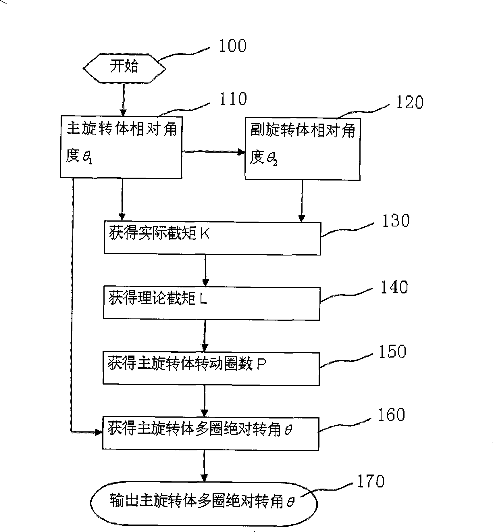
[0041] figure 1 It is a flow chart of a measurement method for the steering wheel angle of an automobile. The steps of this method are:

[0042] Start (step 100); obtain the relative rotation angle θ of the main rotating body 1 1 (step 110) and the relative rotation angle θ of the auxiliary rotating body 2 2 (step 120); obtain actual intercept K (step 130); obtain theoretical intercept L (step 140) by actual intercept K; obtain the number of rotations P (step 150) of main rotating body 1 by theoretical intercept L again ; The number of turns P of the main rotating body 1 and the relative rotation angle θ of the main rotating body 1 1 Obtain the absolute rotation angle θ of the main rotator within m circles (step 160 ), and then output the absolute rotation angle θ of the main rotator within m circles (step 170 ).

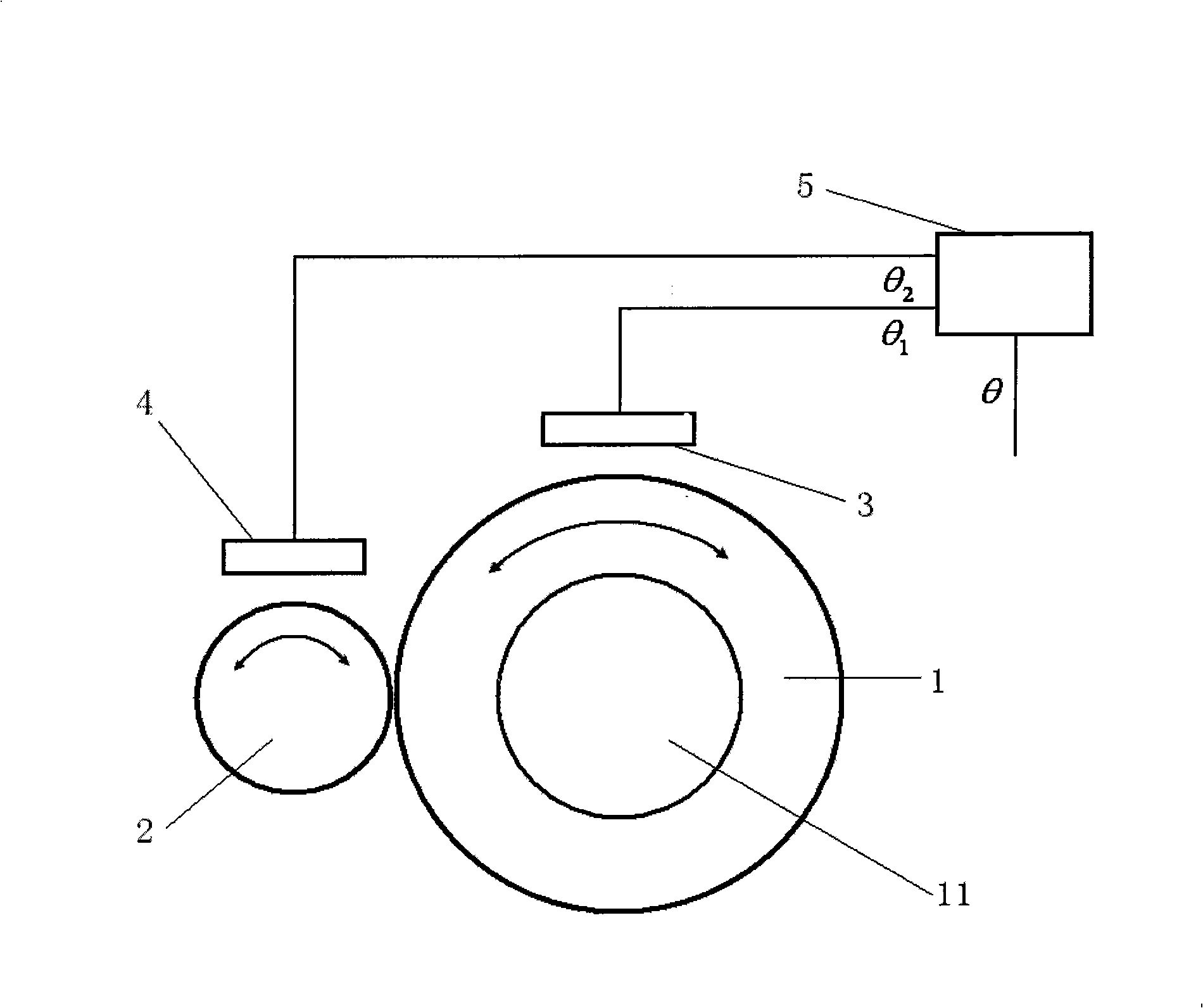
[0043] figure 2 It is a schemati...


PUM


Abstract

The invention discloses a measurement method for the rotation angle of an automobile steering wheel. A main rotation body in the automobile steering wheel drives an auxiliary rotation body to rotate under the rotation driving of a transmission shaft; the transmission ratio of the main rotation body and the auxiliary rotation body is m:n; the main rotation body gains the relative rotation angle Theta1 of the main rotation body by a first rotation angle sensor; the auxiliary rotation body gains the relative rotation angle Thelta2 of the auxiliary rotation body by a second rotation angle sensor, thus gaining practical intercept K; theoretical intercept L is gained by the practical intercept K; the rotation ring number P of the main rotation body is then gained by the theoretical intercept L; the relative rotation angle Thelta1 of the main rotation body and the relative rotation angle Theta2 of the auxiliary rotation body are input into a micro-processor; after processing, the micro-processor outputs an absolute rotation angle Theta in m ring of the main rotation body, namely, the absolute rotation angle Theta in m ring of the main rotation body is gained by the rotation ring number P of the main rotation body and the relative rotation angle Theta1 of the main rotation body. The measurement method of the automobile steering wheel can eliminate the system error which is caused by idle course and realize precisely measuring the absolute rotation angle Theta in m ring in small volume and simple structure.

Description

technical field [0001] The invention relates to the field of sensors, in particular to a method for measuring the steering wheel angle of an automobile. Background technique [0002] The rotation angle sensor is used to detect the position of a rotation angle, and it can achieve high precision in measuring the rotation angle less than 360°. The high-precision photoelectric code disc can achieve more than 20 digits, that is, 1 second. If subdivision is used, a higher resolution can be achieved. However, when the measured angle range exceeds 360°, the problem of determining the number of turns will be encountered. Incremental angle sensors can measure multi-turn angles without reducing accuracy. However, incremental encoders have zero point accumulation. Error, poor anti-interference, power-off memory is required when the receiving device is shut down, zero or reference position should be reset when starting up, etc. Absolute angle measurement cannot be performed, and there a...

Claims


Application Information

Patent Timeline
IPC IPC(8): B62D15/02G01D5/12
Inventor 陈池来梅涛汪小华张涛梁华为倪化生陈茅林丙涛李庄李继来
Owner HEFEI INSTITUTES OF PHYSICAL SCIENCE - CHINESE ACAD OF SCI
Why Eureka
Try Eureka