Co-injection molding apparatus

A molding device and co-injection technology, which is applied in the field of plastic product molding, can solve problems affecting the uniformity and surface quality of products, and achieve the effects of small changes in resin flow rate and pressure, improved uniformity and bonding strength, and improved accuracy

Inactive Publication Date: 2008-11-05
DALIAN UNIV OF TECH
View PDF1 Cites 5 Cited by
  • Summary
  • Abstract
  • Description
  • Claims
  • Application Information

AI Technical Summary

Problems solved by technology

The needle valve can move flexibly to successfully complete co-injection molding. However, since the direction of movement of the needle valve is the same as that of the resin melt, the movement of the needle valve will inevitably affect the flow state of the resin, affecting the uniformity and surface quality of the product.

Method used


Image

  • Co-injection molding apparatus
  • Co-injection molding apparatus
  • Co-injection molding apparatus

Examples


Embodiment

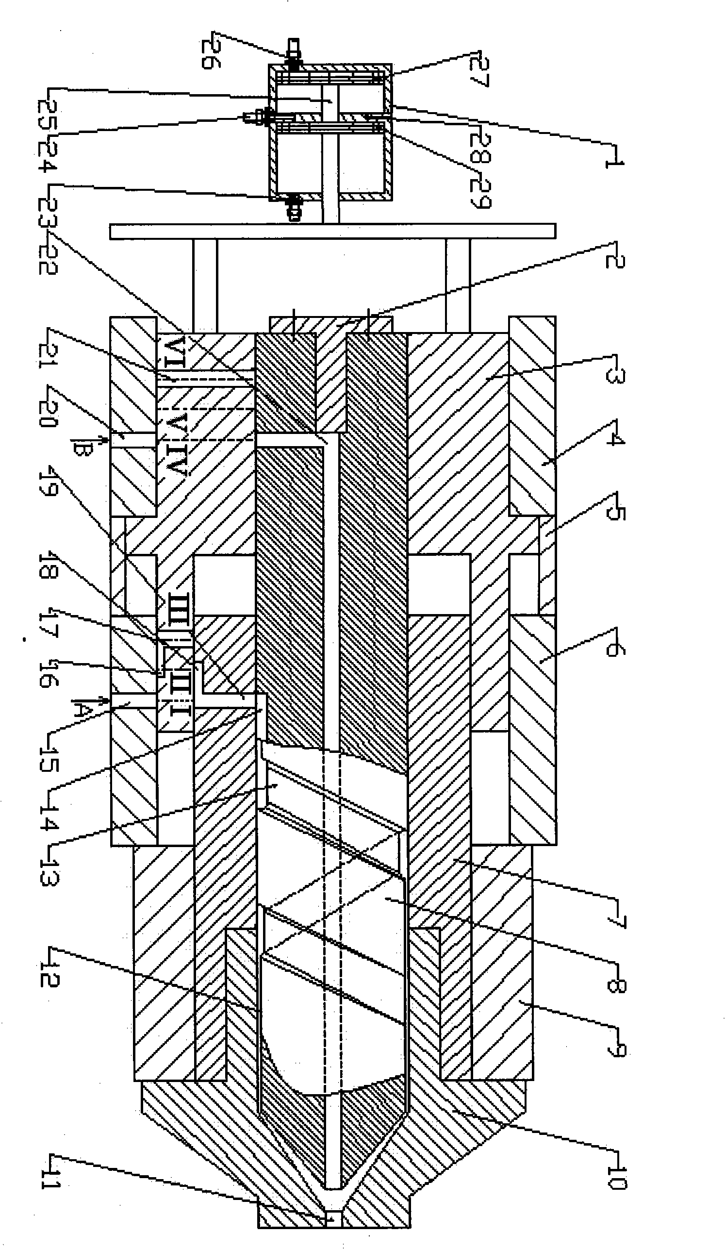
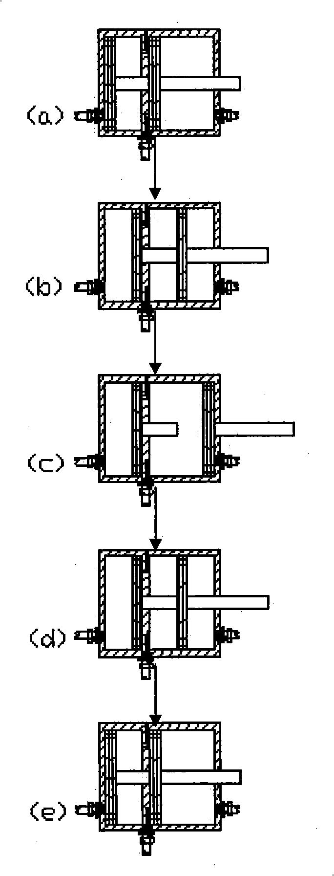
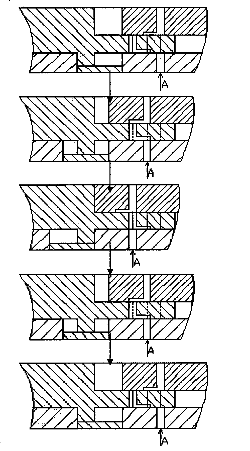
[0016] Before starting work, the unit is positioned at figure 1 location. The outer resin A is injected from the flow channel 15, and the inner layer resin B is injected from the flow channel 20. At this time, the I position of the middle slider 3 is at the flow channel 15, and the position IV is at the flow channel 20. Start to work, release the gas at the right end of the right cylinder from the gas port 23, and inject gas from the gas port 26, push the piston 27 to move forward to the right part of the left cylinder, make the piston 27 move forward for a certain distance, and push the middle slider 3 to move forward, Make the position II of the middle slider 3 reach the runner 15, and the V position reach the runner 20, the lateral opening 16 of the runner 17 is connected with the outer resin runner 15, and the lateral opening of the runner 17 and the runner 19 18 are connected, thereby connecting the outer layer resin flow channel, while the inner layer resin flow channel...


PUM


Abstract

The invention discloses a simultaneous co-injection forming device, belonging to the field of plastic product forming technology. The device is characterized in that a middle sliding block and a cylinder of the device are connected with each other; the middle sliding block can reciprocate with the cylinder; a runner on the middle sliding block can be communicated with an internal layer resin runner on a positioning plate and a central column; the runner on the middle sliding block can be communicated with an external layer resin runner on the positioning plate and a clapboard; the resin which enters the external resin runner passes through a spiral concave trough which is changed from depth to shallowness to flow forwards by uniformly wrapping the central column, and finally flow out from a nozzle outlet by wrapping the internal layer resin, thus realizing the co-injection forming of two resins at the same time. The simultaneous co-injection forming device has the effects and the benefits of improving the shifting control currency of the device, improving the uniformity and the bonding strength of the external layer material and the internal layer material of the product, and solving the technical problem of the product which is produced by one-time forming at a single working position when the injection forming machine injects different external layer material and internal layer material. The core material can be high-strength recyclable material, thus meeting the requirement of energy-saving and exhaust-reduction.

Description

technical field [0001] The invention belongs to the technical field of plastic product molding, and relates to a novel simultaneous co-injection molding device for realizing simultaneous co-injection molding of two resins. Background technique [0002] The cost of raw materials occupies a large proportion in the cost of plastic products. With the development of plastic molding technology, higher requirements are put forward for product performance. Co-injection molding is the most promising advanced plastic molding technology to solve major engineering material problems in the future. Co-injection molding can use the characteristics of multi-layer structure materials to realize the multi-functionality of the product; in addition, ordinary plastics or recycled plastics can be used as the core material of the product, and high-performance materials can be used as the shell material. The cost of the product. [0003] At present, the most successful co-injection molding device...

Claims


Application Information

Patent Timeline
Patent Type & Authority Applications(China)
IPC IPC(8): B29C45/20B29C45/16
Inventor 胡平张万喜梁继才李义李加成梁策柳承德
Owner DALIAN UNIV OF TECH
Why Eureka
Try Eureka